Dynavector
TSR-2
defence cuts failure
Kit No. 0000. 1:48th scale
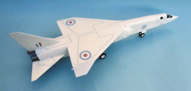
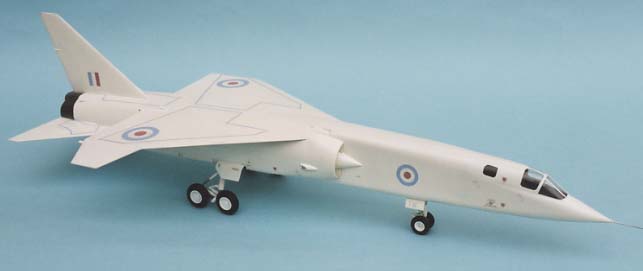
Once again Dynavector has come up with an excellent kit but this time a model of a different breed. This is the ill fated TSR.2 which nearly never got off the ground as it was cancelled by the then minister of defence Dennis Healey before it went into production and has been a subject of discussion among air enthusiasts ever since.The kit, as usual, is of the first order of quality with very crisp mouldings both in the plastic sheets, the white metal castings and the two sets of canopies, it is nicely detailed with delicate panel lines (you don't want them too obtrusive as this is a clean machine). The break down is simple, done with modellers rather than engineers in mind and so there are not too many pieces to cut out,the fuselage is split into four parts, the front half split vertically and the rear horizontally which makes pretty good sense. The main wing is a one-piece structure formed from a top and bottom moulding with stiffeners to give rigidity and the tail surfaces are formed in the standard methodof two halves also. The cockpit bathtubs are simple mouldings, which just need to be cut from the sheet and all the interior detail is taken care of with white metal castings, which makes life so much easier.
After cutting out all the mouldings I cleaned up the workbench to rid myself of all the dust and scrapings, then as this is a large slab sided model there needs to be some stiffeners placed inside the structures and my first job, as instructed,was to add those to the inside of the fwd fuselage walls using superglue,these were simply Tamiya 3mm square rod cut to length. (Photo 1)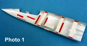
While these were curing I cut some 8mm wide reinforcing beams from 40thou plasticard (you can use the offcuts if you wish), these were cut to length in pairs to suit the fuselage height required and I dropped three in each half, cemented them and left them to harden.
Cutting out the cockpit tubs is a simple job and requires little or no cleaning up as all the details are added later using white metal parts with raised detailing for the instrumentation. I found that a couple of nicks filed into the edges of the front wall (marked F) to match the cockpit sills allowed the whole unit to fit a little easier. Once in position scraps of plastic were cemented on each sidewall below each side console to stop the tubs from ever moving after construction. The tubs and seats were painted and detailed with seat straps from wine bottle foil then fitted to one fuselage half, next the front wheel bay was added with it's bracing and the two halves joined before either addition hardened, a couple of small adjustments were made and the whole piece was taped up and left to harden. Finally I added a couple of cross braces from3mm square rod in the back of this section to give strength where the modelwill be handled and picked up a lot.
The rear halves now need attention, the wheel bay doors area needs to be removed at this stage, drill a few holes and cut the rest away, don't worry as you get separate new doors on the sheet. With a small dab of cement fit one wheel bay in the fuselage and using the main gear leg check that it will seat properly as it can be a tight fit. Repeat for the other side and when you are quite sure the bays are correctly positioned superglue them firmly and brace them as shown on the instructions, you need this as the finished model is quite heavy.
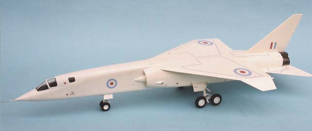
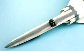
Beams, as shown on the instructions, were superglued in and then taken out again as I wanted to put tabs along the seams. The answer was to cut bits of beam short enough to support the 8mm wide bridges and leave gaps between the bridges to put tabs in topand bottom to match.<> Check the lengths of your bridges to maintain the overall width of the fuselage, I found it to be a shade less than the 62mm recommended and adjusted accordingly. (Photo 2)
Exhaust pipes were made up and odd scraps of 40thou card were cemented to the front end, these supportswere gradually sanded from the bottom until the pipes were level in thefuselage, trial and error here is best. On the real machine the pipes and the fuselage walls are thin sheets of metal so the pipes and fuselage halves of the kit had the rear edges thinned appropriately to simulate this area,before cementing the pipes by the supports only.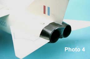
With tabs all in position,both top and bottom of the fuselage were cemented up and again left to harden, this is essential before joining the front to the rear end, when this centre joint was cemented I taped a steel ruler along the undersidecentre line to make sure the whole structure stayed level. The white metal part between the exhausts was added supergluing only the top edge first and the bottom edge was cemented after the top cured thus ensuring youget the correct depth of fuselage at the rear, it sits very neatly between those protruding exhausts.
I did a bit of cleaning up of the joints now, adding just a small amounts of Revell "plasto" filler in a couple of places, it's much easier at this stage before the wing is added.
The intakes and splitter plates were next on the list but before I fixed these I noticed you could seethe horizontal join in the rear fuselage through the intake. I cut a "D" shaped piece of 20thou card slightly smaller than the rear diameter of the intake and cemented it behind the shock cone against the rear "wall" this not only gave a clean blank surface but provided a good location for the intake shell it's self.
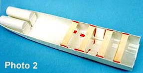
Before assembling the wings you should rescribe the inner edge of the flaps on the lower surface to match those on the top surface and thin down the trailing edges as far as possible on the inner surface then sand a little more on the outer surface after cementing both halves together. Take heed of the instructions on mounting the wing halves building up the stiffeners using superglue. I also added a couple of blocks under the front and rear edges of the fuselage to act as tabs for the top half of the wing to maintain the smooth line at both joins, all the stiffeners were cut from the waste plastic around the mouldings.All the remaining construction work was straightforward and with the addition of tailplanes and fin complete I added a couple of dabs of filler here and there to keep everything tidy. The canopy was masked and cemented in position; you get a spare if you make a mistake, but I found I needed a little fairing in to get a smoothfit but that may have been my fault. Before painting the seams were all checked out by spraying a coat of Halfords primer grey along each to show any defects and this was also used for the base coat on the rear bare metal area ready to take a couple of coats of Alclad II steel which was masked with Tamiya's masking tape. I have looked closely at the real machine in Duxford and decided that Humbrol Hu 130 satin white was a very good match for the overall colour; and I gave the model two coats after which I sprayed a coat of Johnson "klear". Decals are minimal but all were applied with ease and given a final coat of "klear" to finish off with.
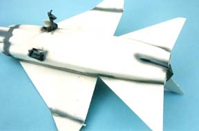
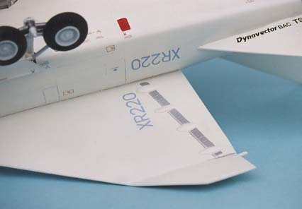
Note the silver areas by the flaps
The all-metal undercarriage is quite complex here and on the real machine even more so if you want to add all the hydraulic lines, I would advise you to mount the nose leg complete with wheels first, add the main legs next and leave to set.
While making up the swinging arm that mounts the main wheels I found the flat angled linkage that fits on the rear of the brakes was a little short to sit nicely so I built a new one from 40thou card making the narrow front length a bit longer and the angle was increasedby 2 degrees a trial and error job again. With the arm complete and wheels added, mount both units on the pinions at the base of the main legs, standon a flat surface and check all is level, now add the superglue makingsure that the wheels are also upright, add the damper arms if you decide on "220" put on the doors and add a pitot tube, I used hypo tubing for mine and there you have it.
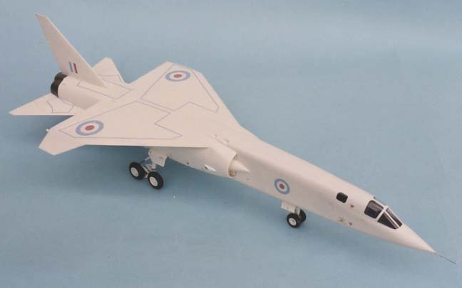
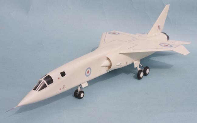
I can't say that the real aeroplane ever inspired enthusiasm on my part before but the model is impressive and easy to make. Most people will not realise that it is a vacuform kit and at 22 ½ inches long it is bound to be noticed on the show tables, I have been converted and am now the proud owner of another fine Dynavector model
Ted Taylor
Sept 2003