Tamiya
F-15E
Strike Eagle
Kit No. 0000. 1:32nd scale
Tamiya
F-15E
Strike Eagle
Kit No. 0000. 1:32nd scale
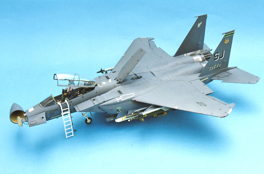
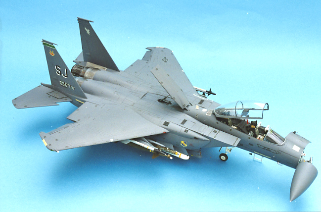
When the Strike Eagle went to the Gulf War theatre, it made quite an impression and I might just say, having built Tamiya’s big Eagle kit, it made quite an impression on me!
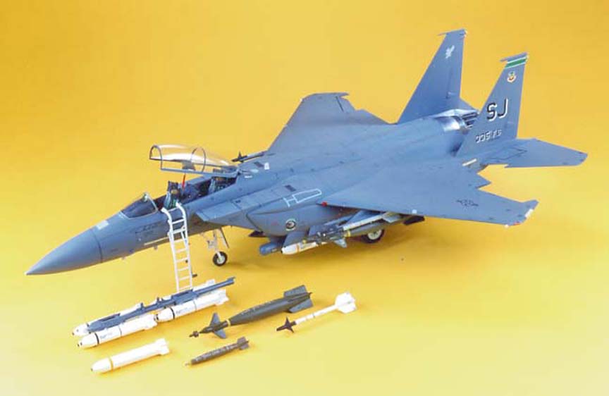
The kit comes in a big box with each and every frame packed in plastic bags, so no damage or loss of parts is likely. The main mouldings are in dark grey plastic, a good match for the real aircraft’s colour of FS 36118 Gunship Grey, but there are also three frames of weapons which are, fortunately, moulded in white, making life easier when painting.
The undercarriage legs are made from a strong metal to take the weight of this huge model and screws are provided to make some of the bigger joints as well as holding the legs, so there is no need for strong glues. A clear frame holds the enormous canopy plus light lenses and CRT (Cathode Ray Tube) screens, all of which are nicely moulded. The canopy, however, has a slight flow mark at the front end, which is no problem if it is raised, but it does show some distortion when viewing it closed.
There are two decal sheets providing markings for five machines, all from the 4th TAC wing based at Seymour Johnson AFB in North Carolina. Three squadrons are supplied, these are generally known as the ‘Eagles’, ‘Chiefs’ and ‘Rocketeers’, names taken from the various Squadron emblems. All are fully depicted in the decal plans at the rear of the 28 page instruction sheet/booklet itself; containing modelling hints and tips, construction sequences (some of which you must stick to), full painting information (very detailed), and even loading suggestions for the weapons which are covered by numerous decals, each fully depicted.
There are some moveable panels and parts along with some alternative pieces, so you can make your model really stand out with what’s in the box alone.
Construction Notes
As you are constantly given paint codes throughout the instructions, cut out or photocopy the paint list on page four and pin it up in front of you for easy reference as you work through. Paint all the cockpit parts before assembly, and note that consoles F28/29 carry the oxygen supply pipes and communications jacks, so if you intend to add them later, drill holes for them now. Part F19 the rear wall, is a sloppy fit, so make sure you centralise it on the cockpit/wheelbay.
Undercarriage
The metal undercarriage legs need priming, but not before you add the extra plastic parts (D40/48 and D41/49) or these might not fit. I gave them a coat of Revell’s Basic Color before using Humbrol’s 130 Satin White as a top coat. The oleos can be scraped clean back to bare metal just like the real thing. There is a small plate at the top of each main leg to accommodate the screw fixing, but it is a trifle oversize for its recess. Therefore, I filed back the front outer corner a little, after which it dropped in keeping the leg at the correct angle, both vertically and fore and aft. The nose leg is fitted early on, but I left the tyre off until the end as they seem to collect all sorts of dirt. Wrap a piece of masking tape around the leg to cope with spraying the main colour later.
Note that the screws holding the wheels on are very tight self-tappers with soft heads. My screwdriver turned off the first one so I used pliers to turn this one to cut the threads into each leg, the wheels can then be attached using fresh screws and no strain (you do get spares).
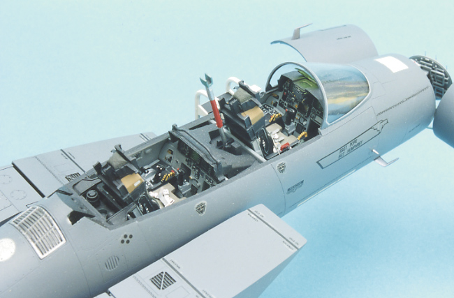
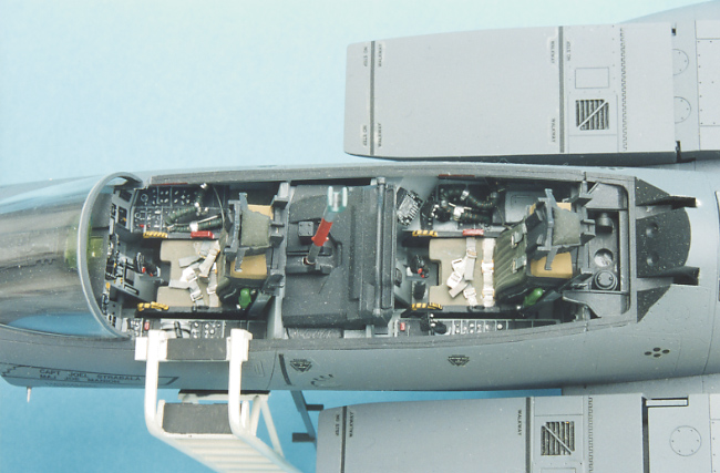
Cockpit
I recommend you spend some time in the cockpit and open bay areas using delicate touches with the paintbrush, you’ll see the benefits later after assembly when they are not so accessible. Two pilots with a variety of arms are provided and if you use them they must be inserted with the seats, they will not go in later. Without the pilots, some seat straps will be required. I made mine from wine bottle foil cut into strips with buckles coming from a Reheat set. The seats can then be fitted at a later stage.
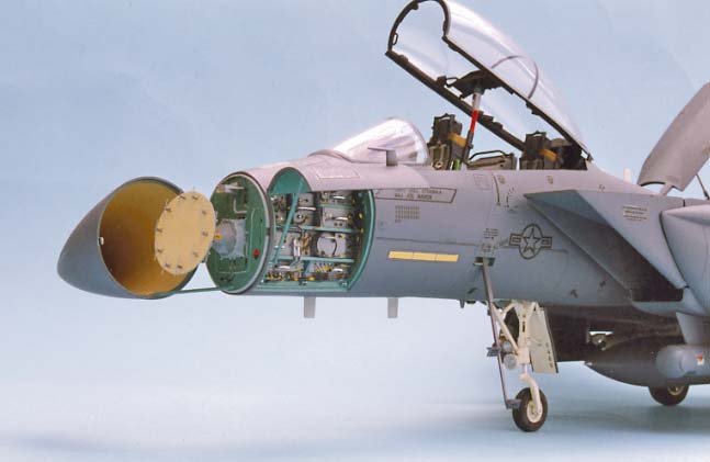
Fuselage
The electronics bay on fuselage half part A2, can stand a little improvement. For instance, the grab handle on each ‘black box’ is moulded solid, so I cut each one off and replaced it with some florists wire fitted into holes drilled at each end. A careful study of photos in the Wings No.1 book on the Eagle will show quite a number of extra cables than those moulded in the bay. I have added some from various fuse wires fixed with a dab of Humbrol’s Superfast epoxy into pre-drilled holes and painted black. Part D25 is a tight fit so don’t paint the edges.
The intakes/ramps made up in Step 12 are handed, so take care when fitting to the air ducts. Make sure that the small grilles on the top surfaces are inboard. The M61A1 20mm Vulcan cannon is a convincing little item in its own right and is worth a little extra effort. I first drilled out the ends of the barrels, not too deeply mind, then sprayed each part with Humbrol Metal Cote Polished Steel. After 30 minutes I buffed them with an old soft rag and they looked like real metal. You can now assemble the barrels and breech mechanism fully, but you must mount the gun before adding the front cover/aperture, part AlO, or you will have a big problem with its insertion.
Whilst I sprayed the cannon, I took the opportunity to spray the exhaust, parts E12, 13, and 14, with Polished Steel. The rag was only used to highlight the details this time. Later, after assembly, some matt black and white was sprayed on very lightly, and in an irregular pattern, to create the sooty interiors.
I find that Rub n’ Buff is one of the easiest products to impart a metal finish on plastic (alclad II now does a better finish). I apply it with the tip of my small finger and keep rubbing until I achieve the required shine. The bright silver finish can then be toned down with Zebrite Grate polish, again using the same application technique. Finally, an overall coat of Johnson Wax Klear is applied to seal it all in. This technique was used on parts E5 and the bare metal areas of the fuselage, which are such a prominent feature of the Eagle. I also tried one area with foil covering, but I was none too pleased with the effect.
As mentioned earlier, much of the fuselage is held together with screws, but you still need cement along the joints. I found that a couple of the screws, when tightened, pulled some of the joints out of line, which would have required filler later. Therefore, I made a point of cementing the seams first and adding the screws later when the joints had fully hardened. All but one fitted perfectly, this being the cockpit to the rear fuselage. The join itself is perfect really, but I accidentally misaligned it by just a fraction, which left me with a minor sanding job.
Seams on the fuselage sides will need a little cleaning up with 1200 grade wet and dry paper to eliminate the join line. However, if you have taken care with the locations at the rear end this should prove quite minimal.
Wings and Fins
Making up the wings could not be simpler, but you will notice that the trailing edges are a bit thick. Trying to thin them down would involve a lot of sanding and loss of detail so I opted to just scrape the rear edge to a more pointed angle using the back of a knife blade. This creates an impression rather than a fact. Make sure the front of the wing tab clicks right home when adding them to the main fuselage and you should have an almost perfect join. After the cement had dried I had to run a drop of white PVA glue into the join to seal a tiny gap at the leading edge area. I also added a little drop to the lower edge of part AlO, the gun muzzle cover. The formation lights, E21, are quite thick, so I sanded them down from the back before mounting them, approximately 7mm forward of the leading edge of the tailplanes, not as depicted on the decal plans.
The fins are handed by means of their tabs, but there are also two locking hooks which prevent removal after insertion. I found that the starboard location hole needed some adjusting to get a perfect alignment of the fin, but I was unable to get it released, so I would advocate the removal of one each of these locks to allow for adjustments to be made. You do not need to fit the fins until after painting and decaling is all complete, much the same as the tailplanes which can be adjusted to any angle you desire.
Ordnance
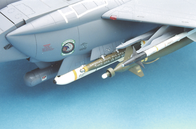
The weapons fit is quite large with some 27 Mk.20 Rockeye CBU and six GBU-10
laser guided bombs, while AIM-9L Sidewinders are provided for defense. One disappointment was the provision of only one fuel tank, but to make up for it both Lantim pods are included and quite nice they are too. The location pins on the Mk.20s are a little slack, take a little extra care here to get the halves level. Use liquid cement and leave for a few seconds before squeezing the joint together, the oozing plastic really seals and fills the joints making them easy to clean up when hard. Make sure that the lower half, part H17, is pushed right forward to the fuse so that the tail fins can be aligned perfectly. I managed to find some Mk.82 LDGP bombs in my spares box which I made up with the Paveway II LGBs, so I could vary the load options.
One feature I particularly liked was the provision of attachment points for the weapons, which come with locator blocks to fit into the ordnance, or with just the ‘steadies’ moulded on, so that you can depict empty pylons if you wish. Each one has a good strong, well thought out locator, so there is no painstaking scraping of unwanted paint, nor will they fall off later. All my stores were added to the rails or pylons before these were attached to the aircraft, I feel it is easier to work that way. The Lantirn pods are little gems with separate cooling intakes and lots of decals, these are mounted beneath the intakes, but not always are both carried. During the Gulf War the targeting pods were scarce and often the aircraft flew in pairs, the lead ship with the pod, would laser mark for his wingman to drop his LG bombs, but both would have the navigation pod aboard.
Just a word on the weapons loads. According to my good friend Jim Rotramel, the three main pylons in the kit are mainly used to carry fuel tanks (although cleared for weapons), and although the MER-200 bomb racks were fitted on the Strike Eagle demonstrator (OLD-291) they were deleted for production aircraft in favour of the pylons fitted on the CFTs which can carry up to 12 bombs at one time. The World Airpower Journal’s books on the US Air Force and Gulf War Debrief contain lots more on this subject, which you will find useful as well as interesting.
It is obvious that Tamiya’s research crew looked at bombs used for ground crew training when planning the decals, hence some of the stencils and blue striping. Live munitions are usually denoted with yellow bands even black or brown denoting various dangerous enclosures, so if you want a ‘War Load’ refer to the books above and lay in a store of Xtradecal stripes of the appropriate colour, but don’t use the ‘Load Training’ or ‘Do not Fly’ decals.
Painting
With the main construction work on the fuselage and wings now complete, I covered the silvered rear end with a new masking medium called Parafilm ‘M’ which is available from Aeroclub. This is a waxy looking film which can be stretched to amazing lengths and laid over the area not to be painted. There is no adhesive on the material, it simply stays there under tension and suction.
The edges or patterns can be cut in situ with the lightest touch of a scalpel. Remove the excess and check that the edges have not lifted by pressing with a finger all around. Later it can be removed without any damage whatsoever to the surface below, an exciting new product. Strips of ordinary masking tape protected my previously painted cockpit and electronics bay, while the unclosed portions of the main wheel bays, which had been painted white along with the legs, were protected by some Blu-Tack.
All items such as fins, tailplanes, pods, pylons, fuel tank and nose cone were mounted on clothes pegs ready to spray. The cannon bay simply had the door placed in position and closed. A word of warning here, the hinge pins on both bay doors, parts AS and A13, are quite fine and the fit is so very close that repeated fitting could strain or break them, so only position them once when needed. Once fitted though, they can be opened without problems.
The overall colour, Gunship Grey, is available in a spray can from Tamiya stockists, but I prefer my trusty airbrush and I used the Xtracolor X130, which has a gloss finish ready for decaling. Humbrol No.125 is the same colour and is a satin finish if you prefer that. For the CBUs I wanted a shiny but not glossy finish, so I made a 50:50 mix of Humbrol Nos. 130 plus 22 and gave each item a light coat along with two Sidewinders.
While these were all drying I did some detail painting which alone took me two days (lots of entertainment value in this kit!). In most places I used Humbrol or Xtracolor equivalents to Tamiya’s colours, but instead of mixing the interior F-15 colour as recommended, I used Xtracolor X159, which is matched to genuine paint chips, especially for this kit (or for any single-seater where Bay 5 is on display).
The HUD (Head-Up Display) screen, part J15, is a peculiar item. The full-size HUD is, in fact, clear, but you can view it from one angle and it looks green, while from another it appears pinkish. I chose the green, using Tamiya’s transparent X25, just one pass of the brush to give a very smooth thin coat which looks about right. The NAV lights and beacons were also coated with the appropriate transparent colours from this range which is excellent for any clear parts. Also, if the backing or mounting is painted silver they will really stand out.
The canopy and windshield require some frame painting; both have engraved frame lines so it is fairly easy. Paint matt black first to give the inside frame colour, then you will find a fine line representing the sealant. Use a lightish grey here before using dark grey on the frame itself, don’t be too careful as the sealant is normally painted, but it soon flakes off. Don’t forget to paint the top inside surfaces of the canopy frame, part G16 and D70, as it will prove very difficult later when the clear part is in position.
Small areas on the missiles need careful painting and two black lines along the CBUs are best done with a flat brush. Just slide it sideways along the surface of the ridges. For the Mk.82 bombs I have used various shades of Olive Drab. Try not to get too even a finish, just like the real thing, and not too much care as they only throw them away! The same applies to the yellow nose area. Check through war photos and you’ll see lots of messages chalked on munitions. I have copied this using a white coloured pencil, the type you can get from good art stores. If you purchase several colours you will find them very useful in cockpits for switches etc. Polished Steel was used both for the Pitot tubes and the outer surfaces of the AIM-9 launch rails, buffed to a good shine.
Decal Application
Once I was satisfied with my painting a coat of Klear was sprayed over the various parts. This when hard, helps to protect the paintwork from handling marks during the decal application. The decals are excellent both in detail and quality, they are also very thin, so the use of a soft brush to place them is advised. To avoid confusion a number of top surface decals are depicted numerically on one side only, but from the drawings it is obvious that they are on both sides, i.e. ‘no step’, ‘no push’.
When applying lots of tiny decals such as these, there is a tendency to get some silvering and to overcome this you have two choices. You can add a dab of Micro Sol or you can use a dab of Klear under the decal, which will eliminate the problem. In the case of the air refueling door, once the decal is pressed down in position and dabbed with a cloth, but not yet fully dry, run around the interior of the outline with a scalpel point and lift out the excess decal film with a soft damp brush.
If you use the crew steps, part 69, note the bottom of decal 95 should be cut off while still dry to fit half onto each step. Decals 128, 129 are handed the ‘TH’ being shadow shaded, so don’t get them mixed up. I have not used the light strip decals, as bright yellow is not the right colour. A good substitute can be found on Detail and Scale sheet 0848, available from Hannants of Lowestoft, or alternatively, you can paint them using a very pale yellow. Note that on the rear fuselage an extra light has been added to the standard two bars previously fitted to F-15s. Use a drop of thin dark grey paint to outline the wing tip strip lights, just run it into the engraved lines provided. Once the decals are dry with no silvering, spray a coat of Klear over everything to seal in.
Spray a coat of matt varnish over all to get the degree of finish you require. I like to get a nice sheen, so mine is just a thin light coat.
Final Details
Finish off the main construction and remove all your masking before turning your attention to the cockpit. Although well detailed, there is just one thing missing, the oxygen supply pipes which also have the communications cable taped to them. These are not too difficult to make in this scale. I found a length of plastic coated multi-strand bell wire, approximately 1mm ip diameter. Take a single strand and coil it around closely, approximately two inches of wire, then brush paint with Olive Drab. The paint will blend the wire in to give a reasonable effect. Lay another strand of wire alongside the pipe and bind it with thin strips of tape to represent the mike cable. Cut in half and fix into the previously drilled holes on the consoles. Bend into a small loop and adjust the length to suit. There are good reference photos in Verlinden’s Lock On No.4 on the Eagle for precise details and positions.
There is a fine mould line on top of the canopy that can be sanded away with 1200 grade wet or dry. You can restore the finish with Final Touch canopy polish or you can ignore it as it is quite faint.
The radar is the last item to be fitted to avoid damage. It is nicely done, but it can be easily improved if you desire. Part D8, the planer antenna, has 10 very basic dipoles moulded on the front surface which should be surmounted by small wire coat hanger shaped antennas. Hard to reproduce, so I have just super-glued small lengths of fine fuse wire across the top of each pole which gives a reasonable likeness.
On the radar base plate, part D9, the projection at the top is supposed to be the flood antenna, but it is not the correct shape due to moulding limitations. It can easily be corrected with a couple of pieces of scrap plastic (check reference photos). Remove the original, clean up the base and cement the new parts in position and paint light grey. Pop the nose cone on and there you have it.
One final point for those who are thinking of making a Lakenheath (LN) based machine. You will need two large air intakes which fit below the wings on the fuselage sides, I believe these are only fitted to LN aircraft.
Summary
The ultimate in aircraft kits at the present time, albeit with a hefty price tag (£100). However, you get a lot of excellent model for your money with many evenings pleasurable work and no real problems - unless it comes to display space! This is one of those kits you cannot make a bad model from, but you can still put your own individual mark upon it with the alternative parts supplied or a little extra detailing.
References
F-15E Strike Eagle by Hans Halberstadt
published by Speciality Press.
Datagraph 6- F-15E Strike Eagle by
D.R Jenkins published by Aerofax.
Lock-on No.4 - F-15C/D Eagle by Willy
Peeters published by Verlinden
Publications.
Lock-on No.22 - F-15E Strike Eagle by
Willy Peeters published by Verlinden
Publications.
World Air Power Journal - USAirForce.
World Air Power Journal - Gulf War
Debrief
The (J5..4F Year Book 1993 contains a
feature.
Superbase Books 12 and 23 published
by Osprey Publications.
Striking Eagles by Andy Evans - Scale
Models International, October 1992. •
Ted Taylor
April 1994