Hachette Part works
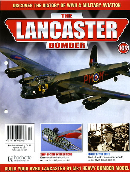
Lancaster Bomber
125 Part construction kit
1:32nd scale
Part 1
Hachette Part works
Lancaster Bomber
125 Part construction kit
1:32nd scale
Part 1
Just after the war as a young lad I built balsa wood planes, solid and flying models, but then plastic models came along and I have kept with this medium ever since until two and a half years ago when I saw this advert and thought that is a good Idea and it took me back to the flying scale days of formers and stringers and tissue paper.
This model is made from plywood formers and plastic stringers and covered with very thin sheet aluminium metal, It is of course a part work kit in 125 parts and each week it comes with a sheet of ply with laser cut parts which just need a snip to release each part plus other parts needed to complete that section. A booklet with explicit instructions on the build and some histories accompanies each packet.
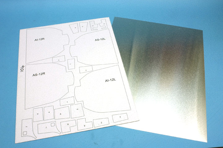
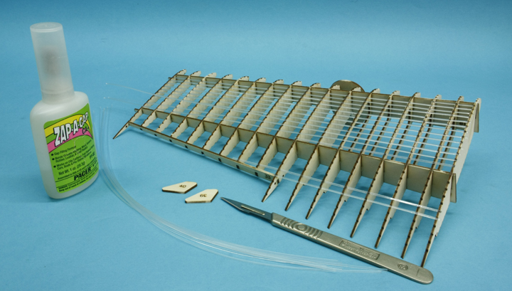
I looked forward to the formers and stringers but dreaded the idea of metal coverings but in for a penny etc. I need not have worried as the metal can be cut with a scalpel then bent to break each part out or cut with a small pair of scissors. you get a template sheet of stiff card with each sheet of metal to use as a guide just score around the edge and snap it out.
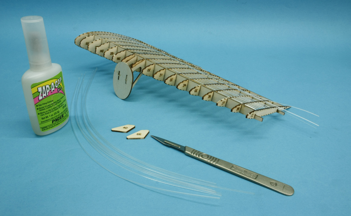
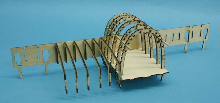
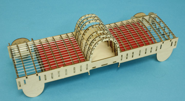
This is the basic construction method, note the size compared to the scalpel
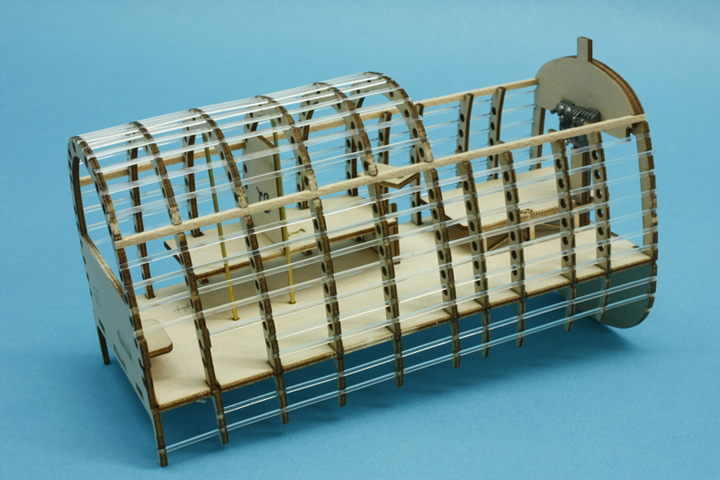
most stringers are in place and the wing is getting quite strong
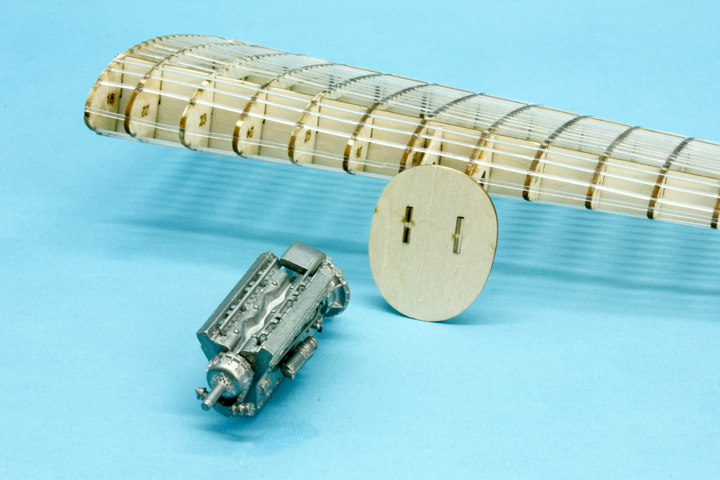
The Merlin engines are made up from tough metal much like diecast cars but are quite detailed when all the wiring and pipes are added
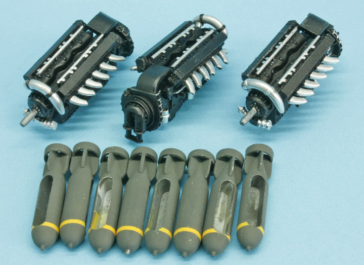
The other engines and some of the bombs
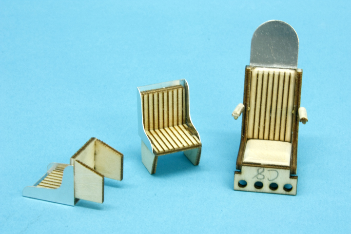
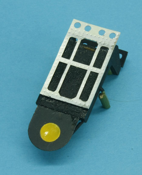
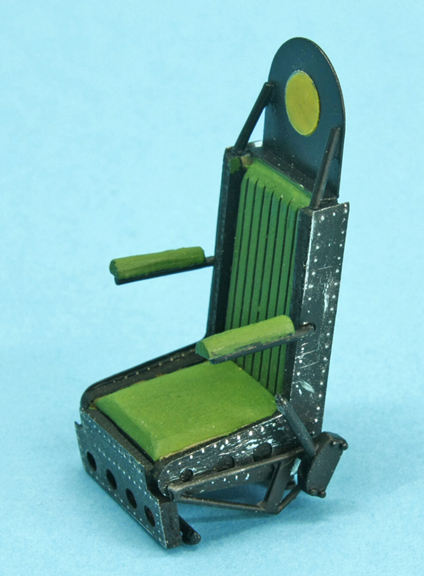
The basic seats more details are to come
a new back for the seat and the final touch
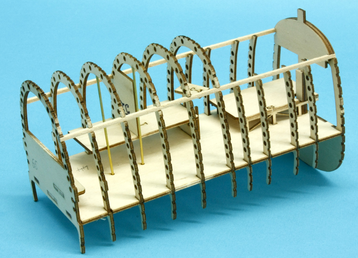
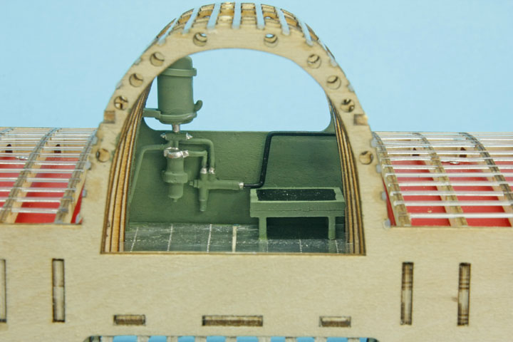
Start of the cockpit area, note the Navigator and radio operator's tables soon to be filled with lots of instruments all added from sheet aluminium and formed into units with knobs and switches etc. etc.
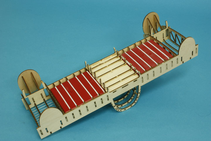
Stringers are now added giving a lot of strength, the area below the floor is a part of the bomb bay
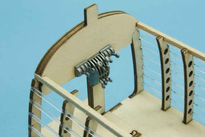
Metal throttle levers, each one was a separate item and is held in with superglue
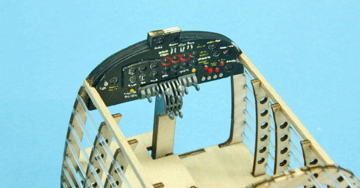
Note the detail on the instrument panel
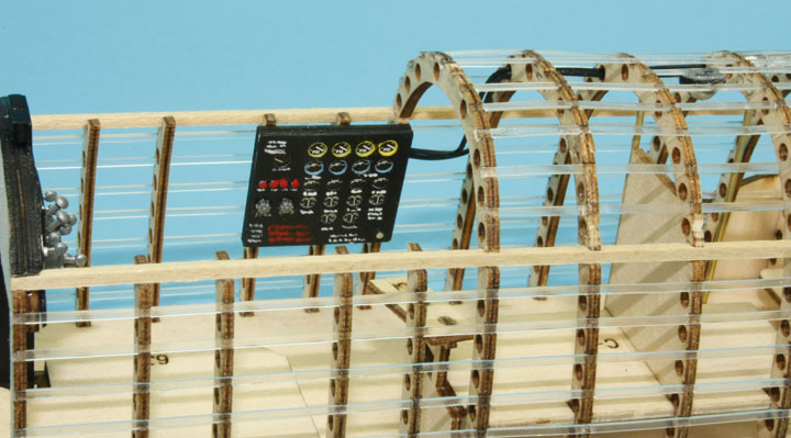
The flight engineer's panel with printed instruments sandwiched between two layers, each knob and switch is added as a separate item
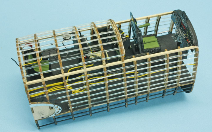
The almost finished cockpit
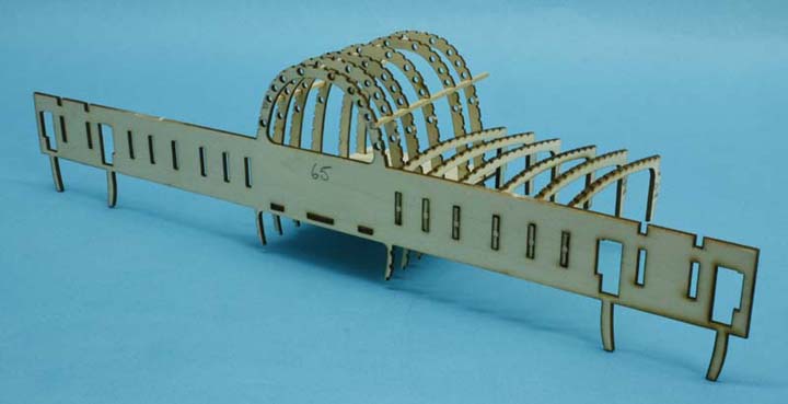
The start of the main spar section, set square needed here to keep every thing square
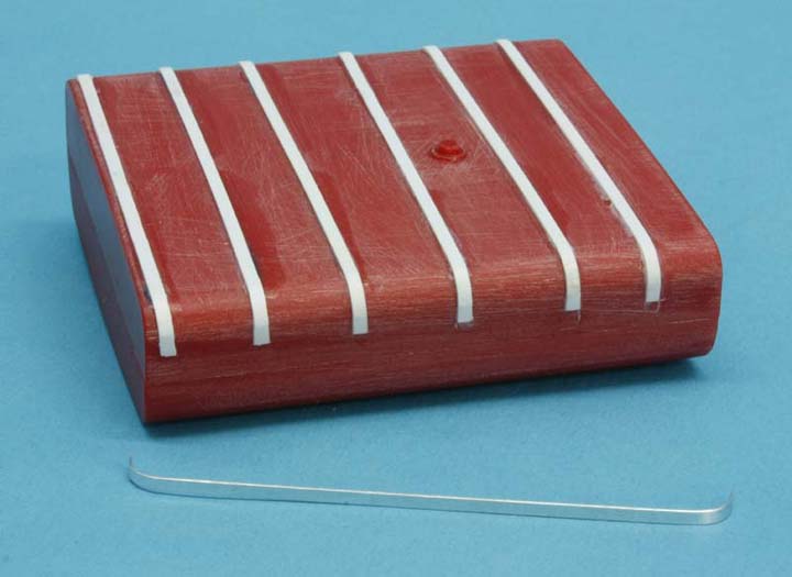
The aluminium strips supplied kept falling off so I replaced them with plastic strip and painted them silver, various pipe lines were added for later locations as each was assembled
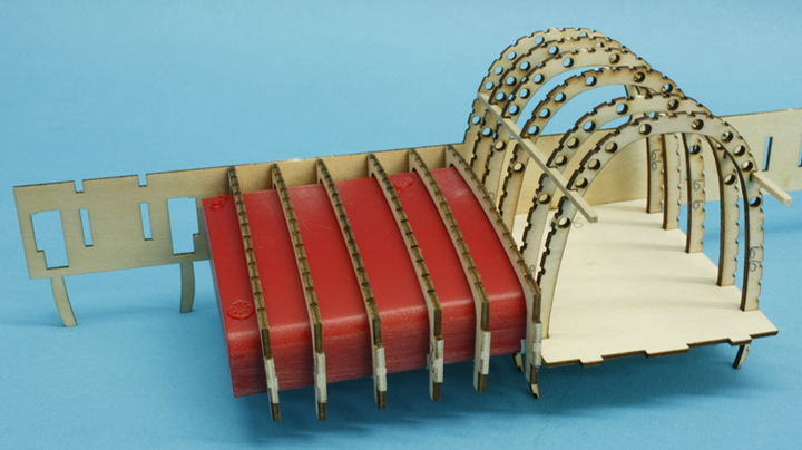
just checking the fit of the fuel tanks
Here they are in position
there are removable panel on the undersides of the tanks for viewing
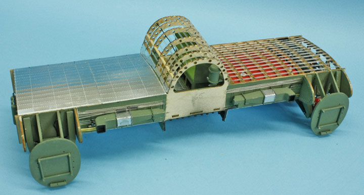
This is one of the leading edge cooling ducts there is another to go on the port side also....
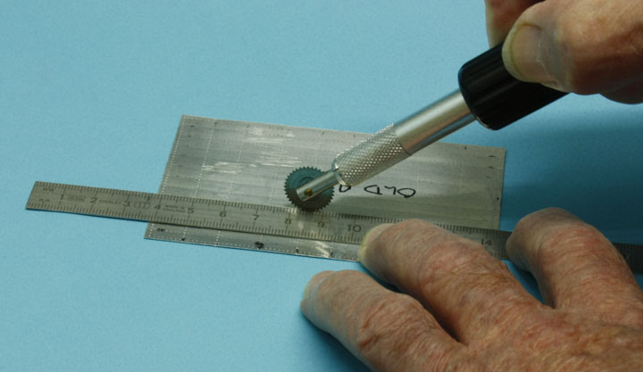
as seen here, note the metal skins on the stbd side, each skin has the rivet pattern embossed on .....
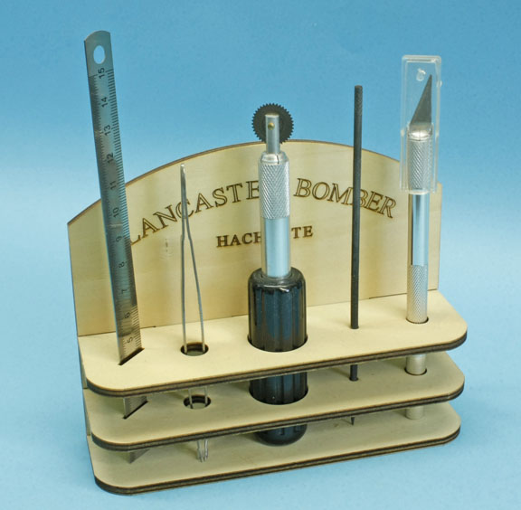
using this tool known as a pounce wheel that is supplied with a pair of tweezers, a file, a knife and a flexible ruler plus a stand to keep them in, one has to measure the positions accurately to match the stringers and formers.
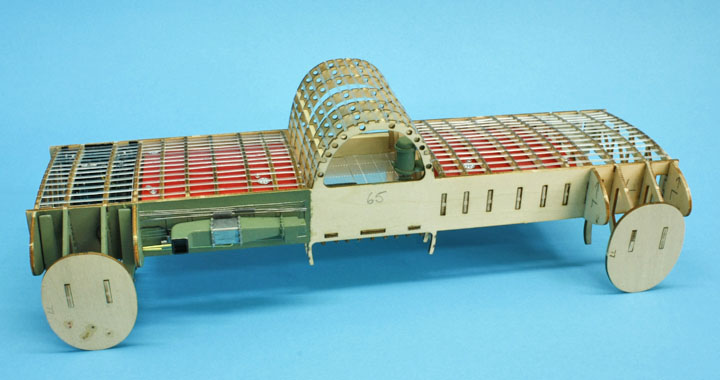
The centre section with some plumbing and a step to get over the spar, the rest bed also fits in here
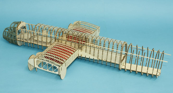
A general view of how the fuselage will eventually join up
That's all for now folks, part two to follow later
Ted Taylor
July 2012