Echelon
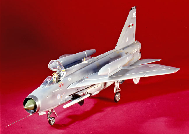
English Electric Lightning
F-6/ F-2A
large Vacuform kit
Kit No. 02. 1:32nd scale
Echelon
English Electric Lightning
F-6/ F-2A
large Vacuform kit
Kit No. 02. 1:32nd scale
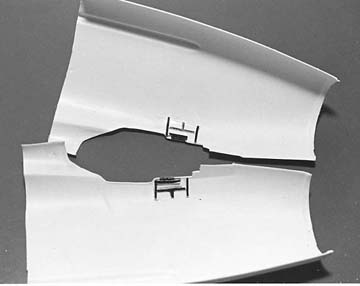
In the first part of the review I dealt mainly with the construction of the main airframe. As this operation had been less demanding than I had thought possible, I decided to add my own stamp on the kit by adding some extra detailing that is beyond economic inclusion in the kit.
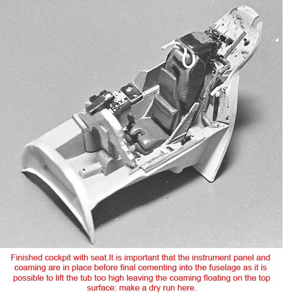
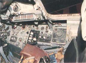
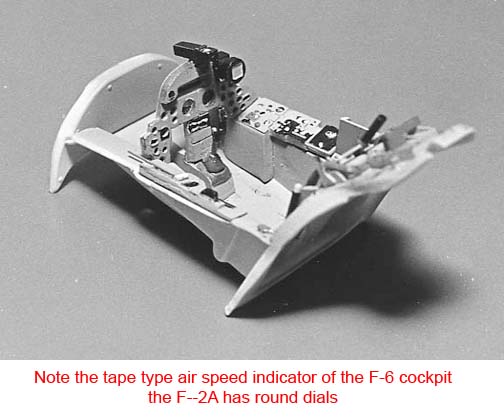
The cockpit is the most visible area and it was here that I started. Armed with a lot of photographs and some scrap plastic strip and rod I was able to make a reasonable representation of a busy work place. While I have not constructed every single pipe or wire, I have attempted most of the more obvious items, which are shown, in my diagrams.
First items were the ribs on the side walls which I made from 60 x 60 thou strip lightly scraped and bowed to match the side wall. At the same time, I added the long box of warning lights just below the coaming on each side. (see photo)
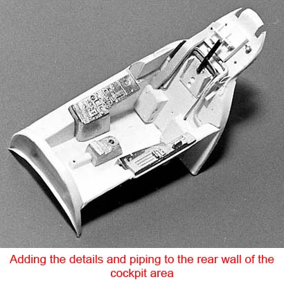
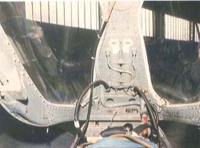
The rear wall of the cockpit was next for treatment. There is a large bar across the rear slope with bearings and cams mounted at the ends, which are connected to, and operate the canopy locks. A large pipe runs across just above this and down the port side, this is the demister pipe and I made this from Plastruct TB1. The plate behind the seat with a couple of holes at the bottom, carries a small piece of rod, but this is only a representation of part of the ejection mechanism - a small cable runs from the top of it to the canopy.
<> The box arrangement on the rear slope is fairly straightforward, made up from various thickness’ of plastic card and the large trunking which runs down the starboard side from it was from 60 thou card slightly bent to shape. A small section behind the starboard overlay needs to be boxed off, 20 thou card will suffice. Add a small piece of fuse wire in front of the throttles to represent the push rod and you now have a convincing cockpit bath.
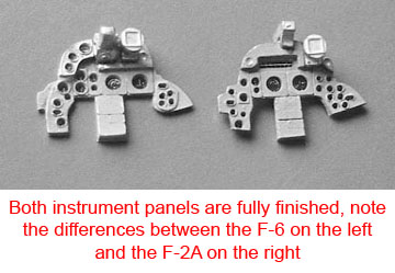
Make up your instrument panel by sanding away the back surface until the holes are clear. Try to get it as thin as you can and use a mouse tail file to clean up the holes. Place the instrument decal on a piece of 10 thou card, line the metal part up with the faces and fix with super glue or the like. When it hardens off, trim the card to match the metal part, add the gun sight and attack radar before mounting on the plinth and side overlays.
There is room for a pair of rudder pedals if you want them, but they will be almost invisible when fitted. The overall colour of the cockpit is a medium to light grey - try Humbrol 128 with various panels and switches picked out in black or white.
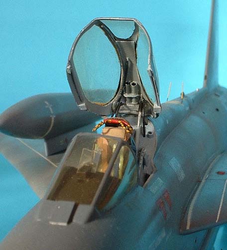
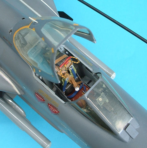
The kit provides two canopies, one in white plastic and one in clear PVC. As with the original Hunter kit, you can choose how to use them. I personally found the PVC item so well defined that all I needed to do was paint the framework on the exterior, (the yellow chop lines are provided on the decal sheet). A metal hinge is provided for those who want to show the canopy open. Carefully separate the windscreen from the rear portion and add the hinge using epoxy resin. Some detailing can be added on the inside and I used the plastic canopy. Carefully cut to slightly smaller dimensions plus the recess for the hinge to give some thickness to the frames. Remember that the Lightning canopy is "double glazed", and you will probably need a smear of epoxy resin to fit it to the PVC item.
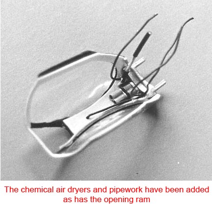
Ordinary cement will not touch the PVC at all, but with the plastic insert in position, the details can be added with Mek Pak. The item that stands out most in the canopy are the two chemical air dryers above the pilot's head. I made them from two small lengths of Contrail tube, 60 thou I think, a couple of straps from foil or Sellotape, and a small wire 'pipe' run across them look convincing. Two short pipes run from the bottom of these to the rear cockpit wall and a third cable runs from the 1FF blade aerial, also to the rear wall. These are all black, but a grey demister pipe runs along the top of the starboard window, front to rear, then across the hinge and ends on the port side, where it makes a connection on the rear cockpit wall when the canopy closes. A small triangle of plastic will make the anchor point for the canopy ram. And there you have it.
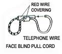
The seat provided is indeed quite excellent, all it needs is the face blind cords and seat straps. Colours are as follows: rocket pack, para pack pan and head piece are black; the seat pan is Light Grey -Humbrol 728; the cushion is Brown 133; the para pack itself is Green 86, as is the drogue pack; and the lumbar cushion looks good painted with 163 Dark Green. The seat straps are quite complicated and I am still working on them, but the face blind cord is easy to make using a short length of telephone wire.
Strip off most of the covering leaving a tiny bit in the centre, bend the wire to shape and insert both ends into another longer piece of covering and cement the lot to the head box. Paint accordingly.
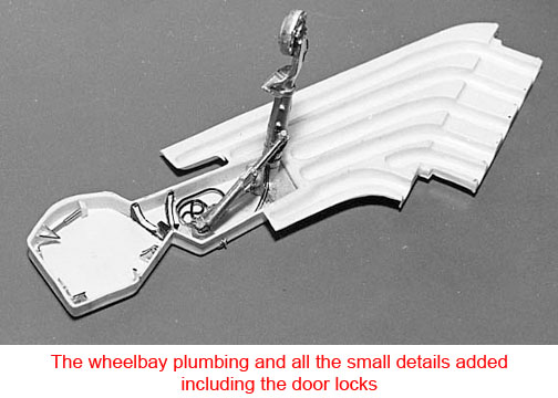
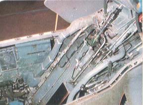
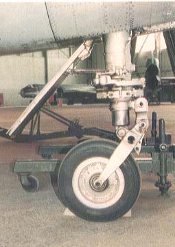
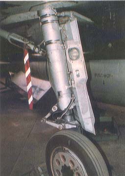
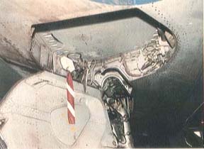
The main undercarriage bay always looks good when further details are added, although there is not too much in the Lightning bays, but a few wires to represent hydraulic lines and some small structural details will work wonders. First of all, the main leg. Just under the curve of the wheel yoke (arch), there are two tiny protrusions of metal, DO NOT remove these, as these are stops to keep the tyres at exactly the right angle in relation to the leg, quite important on this particular aircraft. Drill two tiny holes to take fuse wire in the brake actuator on the main disc. Super-glue 2 x lOOmm lengths of 5 amp fuse wire into the holes and run them up the leg as shown in the photos. Carry the wire across to the rear wall and pass out through a group of previously drilled holes. The radius arm has one pipe up to the elbow joint, which also runs up the leg following the others.
includingI added a couple of small blocks on the main jack, these are drilled to take wires. Loop them round, then pass them over the details added including the jack body and out of the rear wall, (there should be about six pipes, but 1 only managed three without crowding). Plastic card ribs were cut from 60 thou to patterns shown, and other small bits and bobs from 15 thou card, all of which are outlined in black.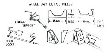
Nearly all of this detailing can be done before major construction begins, but items such as gear door hinges, small intakes and outlets are best left until all the final sanding is completed -when they will not be disturbed.
Last Page
Airbase
What's New
Home
Reviews
Next Page