Echelon
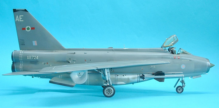
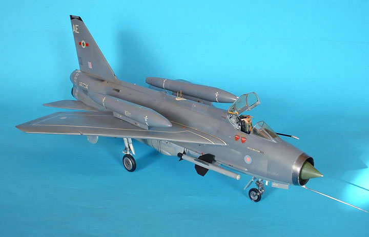
English Electric Lightning
F-6/ F-2A
large Vacuform kit
Kit No. 02. 1:32nd scale
When Echelon released their 1.32 scale Hawker Hunter kit I was rather impressed with its favourable reviews and the large scale was to my liking. However, the subject was not my favourite so I passed it up.
When it was announced that the next Echelon release was to be an English Electric Lightning I took the plunge and asked if I could review it. To my surprise they agreed and said that it might be interesting for a non-vacformer to try his hand and see what came out. I must admit that this is my favourite aircraft, even more so than the Phantom! And I must also confess that I didn’t know as much about the aircraft as I do now.
The kit comes well-packed in a good strong box (for all you mail order fans) and contains four large sheets of formed plastic and a comprehensive instruction sheet which requires careful study as it explains lots of finer points about the kit’s construction.
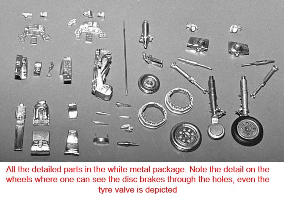
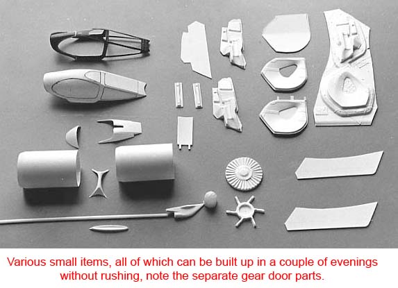
There is also a whole lot of white metal castings, which are some of the best I've seen anywhere, and a decal sheet which has to be seen to appreciate the number of aircraft you can build from it.
The vacformed sheets contain all the parts you need with the exception of a few items, such as missile fins and outer skins for the undercarriage doors which you can easily fabricate from thin plastic card. The surface detailing is all engraved so you loose nothing when sanding your joints, although these are minimal as all the parts fit together with a degree of accuracy that a lot of injection moulded kits would do well to achieve!
Accuracy seems to be the watchword of Echelon and it is obvious that a lot of research has gone into this model. For instance, while working on the model and using photos for reference I did not find one panel line missing or in the wrong place. All the mouldings have nice sharp outlines which makes cutting out so much easier and all are laid out in a well thought-out manner. Although a number of parts require the carrier sheet sanding off, some parts, such as the internal formers, have been designed in such a way as to eliminate even this, all you have to do is closely cut them out
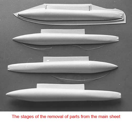
I have in the past only made up various vacform parts, such as fuel tanks, etc., so my skills were rather limited. Therefore, I re-read some of Geoff Prentice’s hints and tips. I tend to agree with him that cutting out parts leaving an 1/8in. border and rubbing around on a flat surface with wet and dry waiting for a flap to fall off is very boring! therefore, I devised my own method which took about 15 minutes to work out and removed the parts from the sheet very accurately and quickly. In fact, I built one airframe, without internal details, in about 20 hours from start to fully sprayed finish!
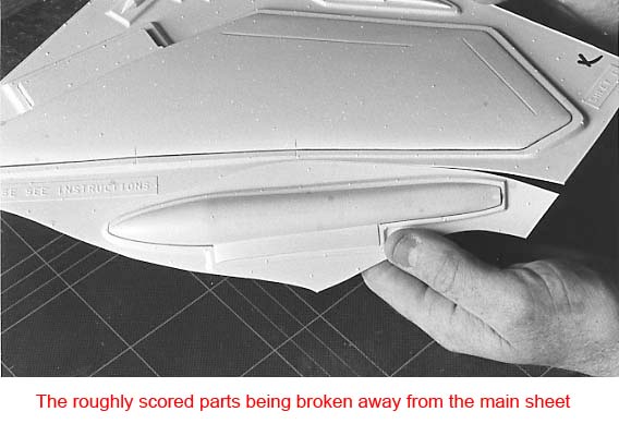
Basically, I roughly score around the parts and break them off the main sheet then I run around the outline with a fine “pilot” pen which will get right into the corners. Next, using a good sharp modeling knife, I make a 45 degree score all around, real close to the pen line with plenty of out cuts. By “out cuts” I mean frequently running the knife out to the edge of the plastic, then when you break it out there is no danger of the part accidentally tearing. Then I just break the part out of the sheet, which is then ready for sanding off the excess. I use a short 1/2in. x l/2in. sanding block with grade three garnet paper held at 90 degrees to the edge. Hold the part so you can see the interior and begin to sand off fairly heavily, after a few strokes the ink line on the exterior begins to show through. Sand only lightly now until the line is pretty clear and move along until you have been all the way around. With gentle strokes you should now see the ink and little hairs of plastic start to fall off.
You have now arrived at where the kit’s designer wants you to be, with parts much the same as any injection moulded kit, though with a thickness more akin to the real thing. Using this method I have not over-sanded or mis-shaped a single piece; in fact I was most impressed to see how perfectly round items such as the radar bullet and missiles have made up. Another way to check the sanding limit is to use a thumbnail across the edge to check if there is still a lip. If one is still present sand lightly until it gets floppy and drops off.
One thing I have learned during this building exercise is not to use too strong a cement or too much of it as a flooded join will eventually burn through the plastic. I personally use Slaters Mek Pak, which is a “gentle” cement that dries quickly. You can put canopies on with this glue without harming them and if you are adding parts after painting it will not harm the surrounding paint if you are careful.
Construction Notes
I built the wings first so that I could check the placement of fuselage formers one and two, which lock the wing tongues in the correct position later on. The Lightning F-2A and F-6 wing is a complicated aerodynamic shape which Echelon have captured perfectly. Because of this you must be aware of the two angle changes along the front edge of each half when sanding them out. Do not lay these items on a flat surface to sand away but note the marks, thoughtfully provided, where the angles change and use a sanding block to good effect.
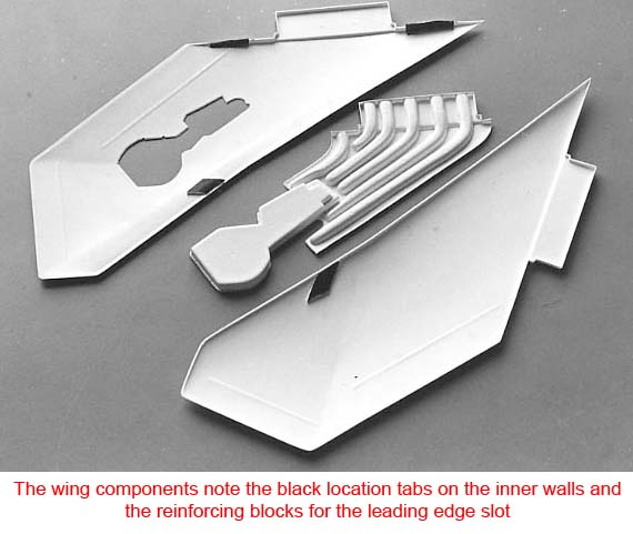
Cut out the wheel bay in the lower wing, getting the outline correct, but don’t worry about the “door” parts as these are to be discarded. Next simply cut around the wheel bay/stiffener ribs ensuring you keep the lip around the edge (marked Black) for cementing.
There is not much in the real wheel bay but now is the chance for the super-detailers to do their thing before cementing to the lower wing, I only thinned the plastic around the hole to get a “thin skin” look, making sure not to flood the ribbed stiffener with cement .
On the inner wing surface that butts up to the fuselage I have placed two 40 thou tabs (shown black) just proud of the surface. These are to locate the top wing half ensuring you keep the anhedral angle built into the lower half. I also added a scrap of 60 thou card to the top and bottom wing, bending to match the shape, where the leading edge slot is indicated allowing one to file it out later without breaking through the surface.
Sand the excess plastic from the tongues, but keep checking until they are a nice firm fit into
the slots of formers one and two.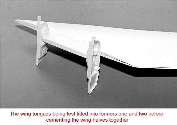
Also, check that there is no distortion of either part. Because of moulding limitations the top wing/fuselage join surface doesn’t have the right angle built in, so just nick the corner of the tongue with a knife which will allow the plastic to bend in sufficiently to meet the tabs in the lower wing to keep the required angle. Cement all around the edges but don’t try to cement the top wing half to wheel bay. When it has hardened off run the sanding block across the trailing edge of the aileron which, on the real machine, is a flat edge tapering from 1/4in. at the outside to 3/4in. at the inner edge where it just turns the corner of the wing and quickly tapers back to a sharp trailing edge for the flaps.
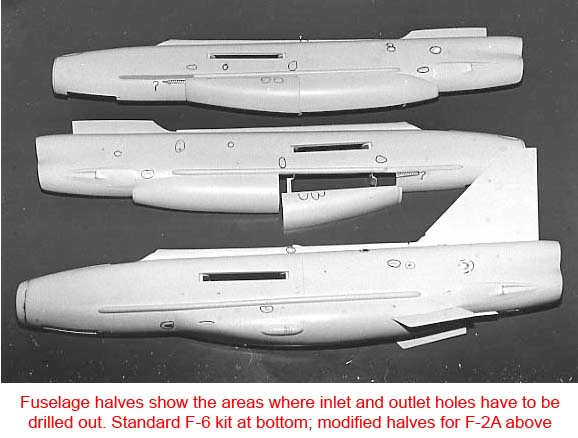
The fuselage looks fairly straightforward but a lot of thought has gone into it to facilitate ease of construction and conversion. It comes as an F-6 with the gun pack in the forward ventral position and long cable duct but, with a couple of cuts you can utilise the alternative forward fuel tank, shorten the cable duct, and open the cannon ports on the nose to produce the alternative F-2A. Luckily both sets of instruments are included! But first, the exterior of the fuselage is covered with inlets and outlets plus various N.A.C.A. ducts, all of which are depicted in the detailing, so I felt it would be nice to open them all up.
To give them a little depth I added some scrap pieces of 60 thou plastic card behind each hole before drilling them through, then backing them off with 15 thou card so you cannot see through. The N.A.C.A. ducts just had the triangles cut Out and backed up with 15 thou card which creates a reasonable impression.The gun troughs were also drilled out, not quite to their full extent, and a small bore plastic drinking straw which had one end cut off at an acute angled curve to match the interior of the trough, this was cut to approx. 30mm in length. This was cemented behind the hole and reinforced with a drop of epoxy resin. The exterior hole can now be filed to its final shape ready to accept the guards later on.
Fit formers one and two into the fuselage keeping them vertical at 90 degrees to the centre line not to the wing incidence line, use the wing tongues as a final check. Former three is only used with the alternative tank arrangement which I will describe at a later date. Former number five holds the engine jet pipes and needs the centre cut out which I did before removing from the carrier, to keep it firm. I also left a flat at the top of each circle to match the engines. Add formers four and five where shown on the plan, I fitted one in each half for stability. There is a centre line on each former so you can get it exact but I found they dropped right into position quite naturally.
<><>
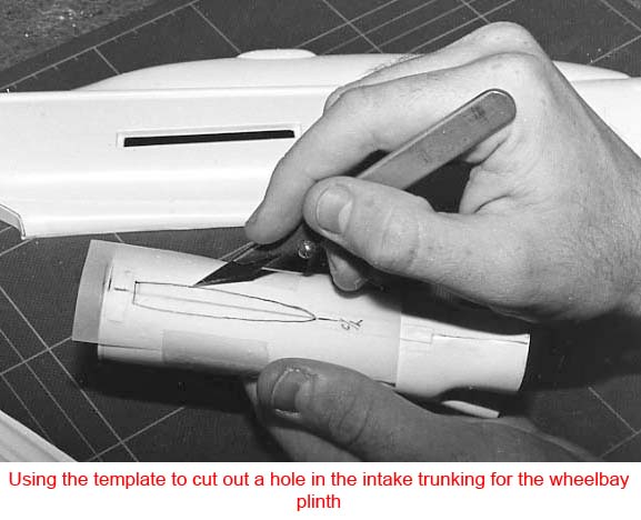
The engine intake is quite ingenious but simple to make. Once you have added the engine face to the lower trunking you can use the template provided to cut a hole in the lower surface into which you slip the combined nosewheel bay/radar bullet plinth just as it is in the real machine. A generous amount of plastic is given around the wheel bay so you can sand it flush after fitting into the fuselage.
<>The cockpit bath sits atop the intake and you have a choice here also, the white metal instrument panels and consoles can be fitted out now or, as I chose, later. The metal seat adds the required weight at the front end to avoid the tail-sitter syndrome.
<><>Both the instrument panels have decals which are to be mounted on thin card, the metal<> Although the fuselage, with its formers, is a strong structure, I ran some narrow strips of 15 thou card along the lower fuselage join to act as tabs to locate the other side and reinforce the join.panel has to be thinned down from the rear until the holes are cleared and mounted in front of the decals making a pleasing effect especially if you drop a brush full of clear varnish into each hole.
<> I just located the intake and cockpit bath while the fuselage halves were cemented together. The fin which I had cut out and sanded earlier was cemented onto its tabs and helped to lock the fuselage together. When this was all taped up, the intake and the cockpit tub were aligned and also glued in position.
<>
That knife edge nose ring, so characteristic of the Lightning, is nicely depicted but calls for a little care.
Remove the part from the carrier along the line depicted which is not horizontal so don’t sand it that way! Cement to the front of the intake lip and leave to harden. Trim out the front web to approx. 1/32nd of an inch from the edge, then use standard Milliput to blend the intake to the ring joint. A wet finger will do most of the shaping but when it hardens, a piece of 600 grade wet and dry can be used to take the Milliput right down to a knife edge. Do take care, however, not to go just that little bit too far The wheel bay can now be cemented to the fuselage shell and, in case you didn’t get it absolutely right, there is an excess of plastic to give a little leeway when you sand it flush. Leave the whole assembly to harden off for a day or two while you make up some of the smaller items.
When the fuselage and wings are set you can lightly rub the whole surface over with 1000 grade wet and dry to remove all the tiny pips and clean up the joins. If you had to use filler then you obviously didn’t make your joint too good so ensure you get back to the original moulded shape. I won’t go into every item but one or two need a little explaining. The missiles are pretty straightforward and only require fins to be cut from 10 thou card. Note on the Firestreaks though, that there is a moulded line along one side. This is where the launch rail fits, so keep to it or the missile will be incorrectly loaded. The missile pylons can be mounted in two ways; either cut the marked hole in the fuselage and insert to the designated line or use the line to cut the pylon to the correct angle to match the fuselage shell. The choice is yours but remember to use the correct pylons with either type of missile.
The undercarriage doors of the Lightning are quite distinctive on their interiors so Echelon have provided the internal detailed shapes to which you just add 10 thou card outer skins. Each item has the lip of the outer skin moulded so all you have to do is sand it to as thin as you can, Cement it to the 10 thou card and trim around the lip - it could not be easier. The ‘D’ door has a little external shape where the offset wing spar is. so I just bent the 10 thou card a little to match the bend in the wing before cementing to the interior. I also left approx. 1/8th in. lip at the top and later cut the three hinges from this to match those in the wheel bay.
The tailplanes have an open end forward of the notch which is purely because of moulding limitations. However, this works quite well matching the fuselage perfectly. But should you wish to “fill” the hole then bear in mind the fuselage shape.The over wing tanks were not used very much on the full-size aircraft, but they are supplied in the kit. You will note from their location that they cant outwards approx. one degree longitudinally and, as they are at 90 degrees to the wing surface with its anhedral, they are also not vertical. This is part of the design, so that when they are jettisoned they will “fly” away from the aircraft without damaging it.
At this stage I added all the little air scoops and deflectors on the outer skin. For this I used some scraps of 20 and 30 thou card, the shape of each piece is engraved on the fuselage so no problems here. Most of the small holes were drilled earlier need small deflectors around them and these I made from slivers cut from small bore plastic drinking straws, use a sharp scalpel and cut a few practice slivers, you’ll soon get the hang of it. Fix them with ordinary cement but take care after as there is such a small surface to cement them to they can soon be dislodged.
Make sure the wing root surface is smooth and flat then cement into the slots. Push them right home and you should have a good join, but if you have a tiny gap, beware, as the wing on the real aircraft is fixed at the centre section only, between the flap and the curved panel line of the walkway; you can actually see daylight through the gap forward of this. At first I left the gap feeling rather pleased with myself until a fellow modeler pointed out my lack of filler, I have since filled the space and I think it looks better on the model - call it artistic license if you like!
An excellent article on Vacform modelling can be found Here
| Last
Page |
Airbase |
What's New |
Home |
Reviews |
Next Page |