Echelon
English Electric Lightning
F-6/ F-2A
large Vacuform kit
Kit No. 02. 1:32nd scale
Ted's Corner
Part
3
Echelon
English Electric Lightning
F-6/ F-2A
large Vacuform kit
Kit No. 02. 1:32nd scale
Part
3
The nose-wheel bay has a few ribs etc. on the inner surface which can be simulated with 40 x 40 thou Slater’s plastic strip. More important though, are four hinges for the horizontal doors which can be made from 30 thou card to give a httle extra strength, they are nearly ‘L’ shaped so that the doors swing clear of the very narrow bay (Sketch 1). A small piece of 20 thou plastic sheet 22mm x 9mm should be fitted to the other door that hangs vertically as a lining. Onto this add two scraps of plastic to take the two rods which fit onto the nose-wheel leg. While in this area there are two aerial blades, one either side of the bay, the port side one is triangular while the other is a longer, straight one.
The pitot tube is made as a detachable item so you can transport the model with ease, it just plugs into a tiny piece of tube that is super-glued into the mounting. However, go sparingly with the super-glue as you can easily fill the tube preventing the insertion of the pitot it'self.
The rear end of the Lightning is literally covered with small inlets and outlets and the Linewrights book is quite useful in this area for the shape of each item, though all the locations are engraved on the fuselage halves.
The Lightning’s tail hook looks a bit like a leaf of an old road spring with a hook on the end. Echelon supply a white metal hook and you need a strip of 15 thou card to complete the piece. Between the card strip and fuselage there is a small block-like arrangement which you can make with a piece of 80 thou card, 28mm long by 3mm wide, cut the rear end with an upward forward facing slope (Sketch 2). When you cut the hole for the hook you need to box the area in. I have used a short length of Plastruct ‘C’ channel cemented inside before you add the lower jet pipe.
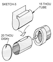
The jet pipes are hollow tubes which have a flat area on the top of each and if you just add the white metal exhaust petals you will be able to see into the fuselage, so I would suggest the following. Lay your white metal part on a sheet of 20 thou card and trim around the edge to form a disc of the same size and shape. Next cut a piece of 15 thou card 62mm x 30mm and roll a tube along the 30mm length, a small tab along the seam will add strength. The tube can now be placed into the rear of the white metal part and super-glued in position. The new disc can be centralised and cemented to the other end of the tube as a blanking plate, (Sketch 3). The whole assembly will now slide into the jet tubes and then into the holes in former No.5.
<> The missiles are very nicely done, but do make sure you match up the halves as directed and also remember the loading line on the Firestreaks. You have to make your own fins from thin plastic sheet, 10 thou would be suitable, but you do get profiles on the instruction sheets to work from. The reason for this is that the 40 thou plastic used to mould the kit is much too thick for items such as the fins and undercarriage door skins. Redtop missiles have a clear dome forming the nose and for this I used a slice of Plastruct acrylic rod, style CAR-S. I used a No.42 drill to make an indentation in the rear face to represent some internal detail and cemented it to the kit missile body with Plastruct’s own Plastic Weld, though epoxy resin will do if this is unavailable. The dome shape was sanded with 600 grade wet’n’dry paper and finished off with 1200 grade. The part was then polished with a new product called “The Final Touch” canopy polish which seems to work very well indeed.
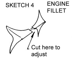
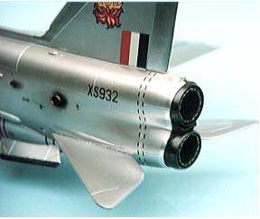
Note that although the engines are staggered, the jet pipes are not, both are level at the rear end. The small fillet between the jet pipes is very delicate, so take care when cutting and sanding. It should just slip between the two, but, if you find you have sanded too much from the fuselage halves or it is just a little too wide, cut down the centre line and sand just a fraction off the two centres, (Sketch 4).
The Firestreak missiles should have clear noses, but they might be difficult to shape, so I have used silver paint instead and the two rows of “windows” around the body are supplied as decals, but look quite effective. A point to note here is the missiles’ usage; the F-6 can carry both Redtop and Firestreak. Of course, the appropriate pylon must be used and the Firestreak must be mounted as directed.
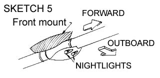
A refuelling probe is provided made from plastic tubing with a lovely white metal nozzle that just pops into the end. The only thing you need to add is the small light for night operations just below the forward mounting on the underside of the pipe (Sketch 5).
Two fuel dumps are required and these I made from a strip of 60 thou card sanded to an oval shape, a 5mm length had 1mm cut off and a tiny rectangle of 10 thou card cemented between the two parts then fitted to the fuselage panels below the wings where indicated (Sketch 6).
All that remains to be done is to add the two spine aerials from 10 thou rod where marked after painting and decaling.
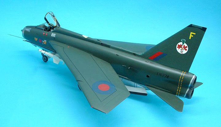
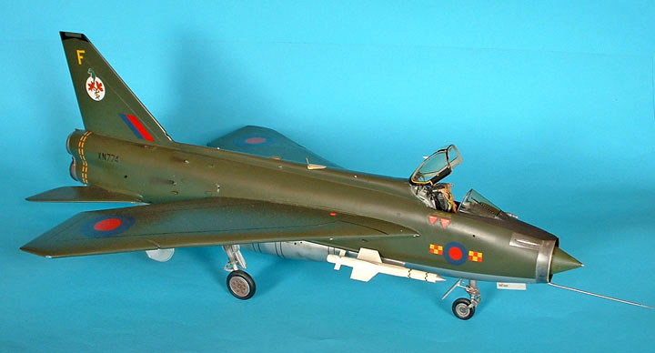
The decal sheet is large by anyone’s standards, shown here is just a part with the decorative items but it also includes walkway lines and those dashes around the rear end. All the roundel types are provided but in this scale, however, I think painting these is more realistic and solves any decal film problems. The lines are easy - just spray the basic colour black, or white, along the area then cut some fine strips of masking tape and lay them where the lines are to be. After spraying the camouflage and removing the tape you will have clean painted lines.
The roundels are still easy, but require just a little more care. I use Frisk Film (a low-tack masking film) and cut a rough three inch square and with a Compass Cutter cut the appropriate circles. Now lay the square over the exact position and lay all the rings to one side, spray a coat of white as a base then put all the rings in position. Lift off each one in turn to spray the colours required and replace each carefully. I think you will be pleased with the results. After completing the decals I have coated the whole model with Johnson’s Klear and over this I have done some weathering.
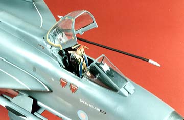
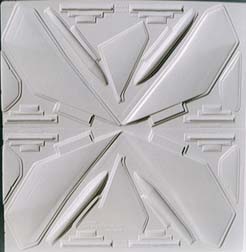
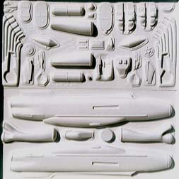
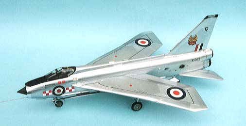
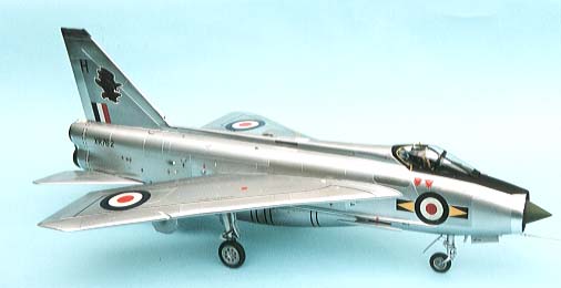
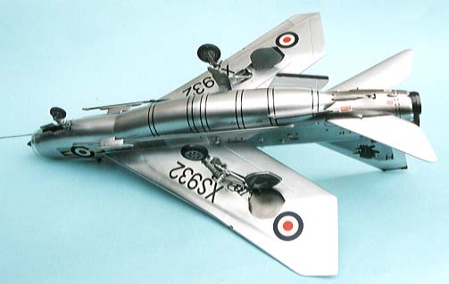
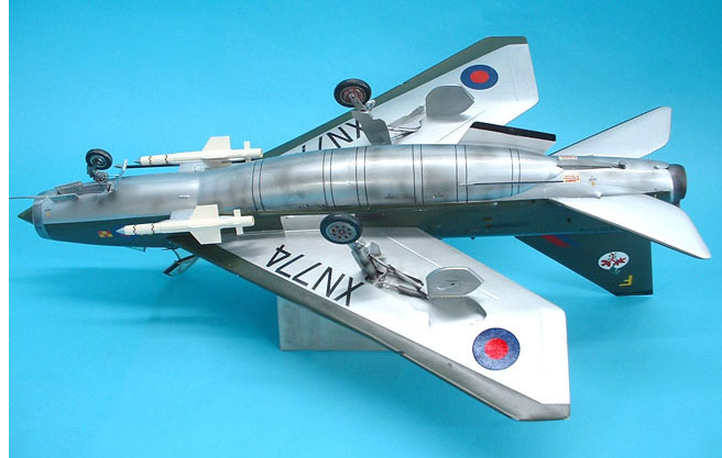
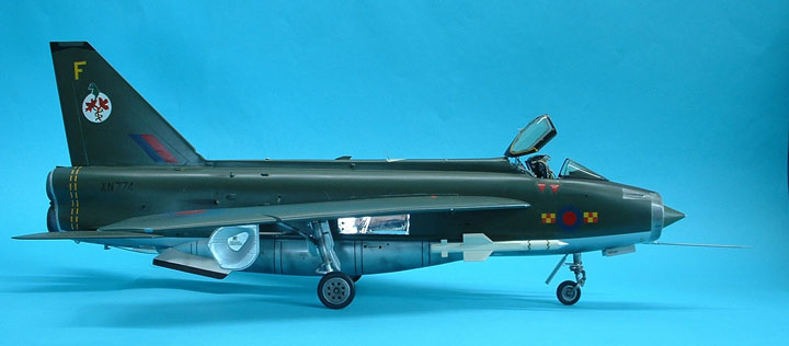
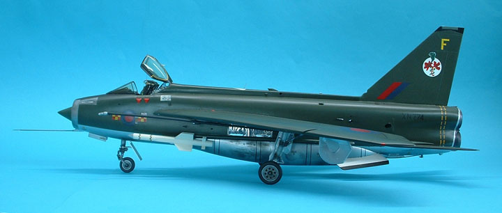
These are the mouldings for the kit straight from the mouldThese photos show the latest I have built using the Alclad II metalizer finishes
they aren't quite as shiny as they appear in the pics
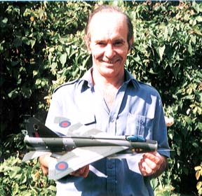
and this is Frank Brown the creator of this masterpieceThe Mk.2A machine looks much the same, but there are several subtle differences. The first item to deal with is the belly tank, and the cable duct which has to be shortened. I found a piece of sprue which was the width of the cable duct interior and cemented it into the front of each duct. When hard I sanded the duct back to the bare sprue which avoids any filler. After removing the gun pack of the F-6, cut down the centre line of former No.3 and cement into each fuselage half, centring on the join line of the new fuel tank to give a solid join. Now trim the bottom of formers’ One and Two to fit the new tank shape - no need for accuracy here though, just clearance. While the halves are separate you can add all the little vents and scoops that you can see in our photos. Note the blocks of plastic inside to give some depth. The gun troughs are now fitted into the upper nose area using small bore straws and epoxy resin. 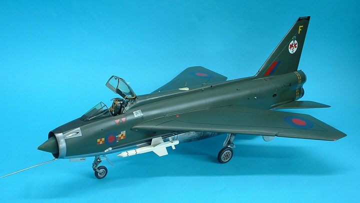
F-2A Version
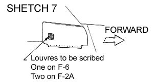
There is one small difference between the F-6 and F-2A that is not immediately very obvious, and that is a small panel below the rear of the cockpit and above the leading edge of the wing. It is a vertical rectangle with slanted Iouvres and on the F-6 it is only fitted on the starboard side while the F-2A has it both sides. These louvres are easily scribed on at this stage with an Olfa ‘P’ Cutter
(Sketch 7).
Just below the windscreen a rectangle with central oval is engraved, about level with the gun trough. Drill out the hole either side as this is to do with purging the gasses of gun fire.
Separate instrument panels are provided for the F-2A with a new larger gun sight, which does not protrude into the coaming; so do not remove the indicated rectangle from it before reading the instructions. The gun sight itself has two glass plates which fold down when not in use, one fits on top and one in the ‘elbow’ above each moulded circle. As far as I can make Out the rest of the cockpit is much the same.
If you do not want your Lightning to carry missiles, the ends of the pylons can be faired over with blocks much as the real aircraft. Do remember that the F-2A wings are not strengthened to carry the over wing tanks, so do not attempt to fit them. Even the F-6s only carried them rarely.
I think I have covered all the major points here, so you can make your own choice of which version to build with confidence.
I think I have built one of the finest models I have seen on the market for many years! It has widened my modelling capabilities an enormous amount, but not stretched my patience at all. I believe this is because of the good fit of the parts and the ease of which I removed them from the carrier sheet - much less of a task than I imagined. Summary
Obviously a very well researched kit that leaves nothing out. You can build a very acceptable model from what is contained in the box. There is room for a little super-detailing, but not very much, unless you want to start opening up panels and baring all.
Sadly Echelon went out of business some time ago and no kits are available now but they can usually still be found at model shows under someones table, I know that many modellers are still a little afraid of vacform kits and have not had the courage to start this one, but be not discouraged as all the difficult tiny parts are provided in white metal form making life so much easier
An excellent article on Vacform modelling can be found here
| Last
Page |
Airbase |
What's New |
Home |
Reviews |
Next Page |