
Hasegawa
F-18C conversion
the old kit updated with Paragon
resins
Kit No. 00000. 1: 32nd scale
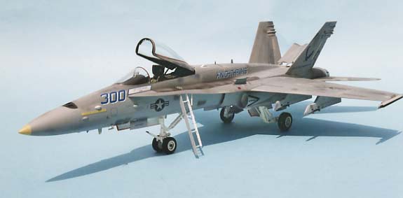
I bought Hasegawa's big F-18 hit when it was first released many years ago, but I was so Disappointed that it was one of the early prototypes, colourful though it was. I have promised myself for some time, that I would do masses of work on it to bring it up to production standard, but there was always something easier or more urgent to do.
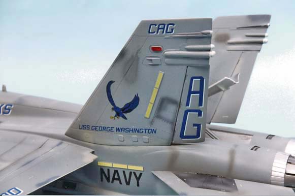
Just recently, the Paragon F/A-18C update set came in for review, and stirred my enthusiasm again. What clinched it was a real pretty sheet of Superscale decals for the GAG (Commander Air Group) aircraft on the USS George Washington, Which visited the UK for the D-Day commemorations, so I cleared the decks (this one is big!) and took a look.
The set contains resin parts, lots of them, and brass etched parts, all of which are nicely produced and well catered for on two instruction sheets. A few of the parts are for the Canadian version of the Hornet and these are also well noted. The first comment I must make is how well all the bits fit without any fuss at all. Of all the detail sets I have tried lately, this is the first where I have used all the bits without a single problem or modification, and what a difference it makes!
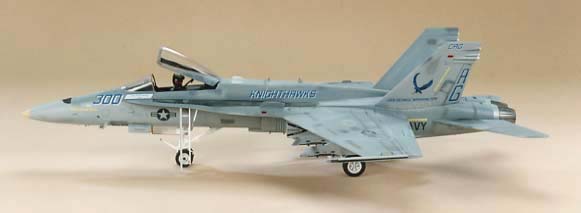
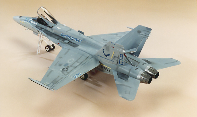
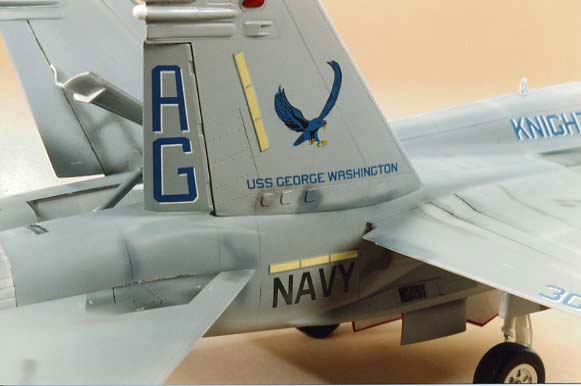
The Superscale decal sheet (32-130) is their latest 1:32 scale release and features an F/A-18C Hornet of VFA-136 Nighthawks. Only one aircraft is depicted, the GAG Bird '300' in its very latest scheme aboard USS George Washington when President Clinton was aboard for the D-Day ceremonies this June.
I have but one complaint; the data around the cockpit area is printed in dark grey and not light, and is a perfect match for the Xtracolor paint used. Consequently it will disappear totally! It might be an idea to do some 'touch-up' painting in the area to provide a little contrast
Construction notes
There is some preparatory work to be done before assembly begins, some of which is a must, but some will be a matter of personal choice.
The ailerons on production F-18s were extended to the full width of the wing so fill the original end lines with super glue or your favorite filler. Later when the wing is assembled you can trim the aileron ends to shape at the same time as removing the dogtooth from the leading edge. Purely from choice I decided to engrave all the panel lines before I assembled the parts. For this I used an Olfa" P-Cutter", a steel rule and some clear plastic strip (to wrap around the fuselage), some tiny dabs of Blu-Tack will help to hold your rule still as you work, correcting any incorrect lines as you go.
On parts B1 and B2, the large vents above the intakes, are moulded open. In reality they are almost always closed, so I trimmed the sides away from mine and dropped them down flush. The lower fuselage, part A4, has two airscoops moulded on the lower surface, remove these and replace with NACA ducts. I fashioned these from 40 thou card.
Brass parts 26 and 27, fit over large holes (vents of some sort), so I mounted a couple of blocks of thick sheet on the inside, above the areas before drilling out the holes to give an appearance of depth. There is another similar hole just forward of the nose gear doors across the centre line, which I drilled, very shallow, with a dentists burr later in the assembly.
Cement the long probe, D19, onto the nose cone and while that hardens, turn your attention to the fins. Sand off the large bulges near the bottom of the rudders and remove the lower ECM bulges (not the fuel vents) on each fin to make room for the new resin parts. After scribing new panel lines I cut out the rudders and repositioned them, slightly offset Don't forget they can be positioned any way, i.e. opposed or both in the same direction.
Fuselage
I now commenced construction by making both front and rear fuselage sections and cleaning them up as required. Mark the centre line on the nose cone for location later, then chop off the front of the probe and roughly cut out the area to accept resin part 12, the gun muzzle orifice. Add the nose cone to the fuselage, clean up the join and sand the front end to correct shape. Now gradually trim the hole until part 12 fits snugly. It is important to go carefully as it's in the most prominent position and will look ugly if not snug. Cement the two halves together, clean up the joins and check that any panel lines tie up nicely. Fill the required holes etc, then you can add the resin fillers (parts 1-4) for the LERX slots. These are handed so don't mix them up, just make sure they fit tightly against the fuselage.
Exhausts
One improvement you can make is around the exhausts. Parts C9 are designed to just pop in the rear fuselage leaving a ‘step’, which actually does not exist. There is no semblance of a tail pipe at all, so I took two 7Omm lengths of Plastruct TB32 and cemented the turbine face, parts C15, to one end and inserted them into the fuselage, ensuring the rear ends are flush with the fuselage. later when you add the nozzles, the 'step' will not be so prominent.
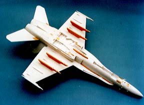
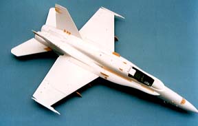
Wings
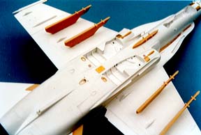
The wings include the LERX’s and will need some reworking. Assemble tops to the bottoms and when hardened off, remove the dog tooth by extending the inner leading edge line right out to the end of the wing. It should be perfectly straight Sand the cut area back to an aerofoil shape, trim the aileron ends as well as cleaning up the inner edges of the flaps to provide clearance for the missiles when loaded. Very accurate measurements are given for the locations of the new resin pylons, also for the outer aileron hinges. Make sure you do this before this next step.
The Sidewinder launchers are moulded too far back on the wing tips, and the wing tip counter balances are not long enough. Saw the launchers off flush with their back edge and remove the counter balances back to the rear of the leading edge slats. Make new ones from 2 x 2.5mm strip, they should protrude 15 1/2in
(scale 12.5mm) from the leading edge and there is a vertical light in the tip which can be painted later. Use a strip of 20 thou card to replace the saw cut, note the pointed shape on the original before sawing. It extends back to the aileron root and carries the strip lights, brass parts 30 and 31, which are handed, so take care with positioning. I have represented the launcher grooves by adding 20 x 20 thou strip to the top and bottom of rail, not perfect but effective. Now mount the modified rails with the rear end level with the trailing edge of the ailerons (see sketch 1).At this stage, the wings can be cemented to the fuselage. I think you will be surprised how little filler is needed along the LERXs to make a perfect job. Leave to harden.
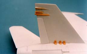
Fins and Tailplanes
Small resin bits are provided for the ECM pods on the fins, but before mounting, cut four small plates (shown in sketch 2), from 5 thou card, add them to the fins ready to take the extra parts, pods which I found needed a little scraping on the inner surfaces to match the fin shape exactly.
All F/A-18s now carry the strip lights on the fins and fuselage. I like to make them from 5 or 10 thou card strip 28.5mm x 3mm. Cement in the appropriate places and after painting add decals from D&S sheets. Cement each fin to the fuselage adding the resin braces 5, 6 and 7 before cement hardens. The fins should lay out by 20° so I cut a sheet of cardboard with a 20° angle, which I used to check until the cement set Don't forget the three tiny plates on the outer fin base.
The 'all-moving' tailplanes have a slot and tab fitting, so you can't deflect them without lots of work, but you may need to shorten the tabs to fit in with those previously fitted Plastruct tail pipes.Final items
All the 'nobbly' bits and grilles can now be added. Roll the grilles, parts 20,21, 22 23 and 24, around a pencil or such, then press each into position on the fuselage – they will prove much easier to fit if you follow this method. The kit AOA sensors are like blade aerials, so they will need a little reshaping for a realistic look (see sketch 3).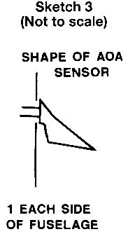
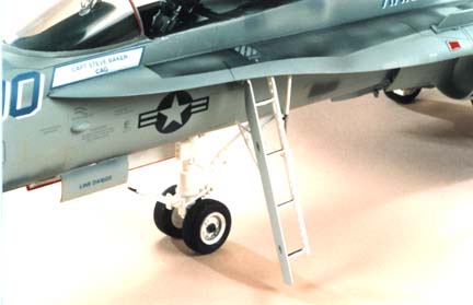
One item that really does need attention is the crew entry ladder. Drill out all the holes in part D24, but don't thin it down as it represents a box section. Cut a new door from 10 thou card using D22as a guide, and cement to the front leg of the steps. No supports or ram are provided, but I made the ‘V’ shaped strut from .75mm rod and the ram was made from Plastruct TB1 with the bottom half stripped of its plastic coating to look like a piston. The top of this fits 12in (scale 6.3mm) behind the ladder on the inner wall of the bay.
The undercarriage is not super-detailed for this scale. It does have some fine points, but not a landing light or the box containing the approach lights, though both are easy to make from scratch and are well covered in reference books.
Painting and finishing
As most construction work was now finished a light spray of grey paint was applied over all joints and filler etc, to check for faults such as heavy sanding marks. These were then polished out and, once I was satisfied, the black walkways were sprayed on freehand and masked using Tamiya's new tape, an excellent product as it has a peelable
Adhesive which never seems to lift the paint.
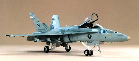
The greys are light and dark compass greys. I sprayed the lighter FS 16375 on the under surfaces and the outer fin surfaces. All the top surfaces and inner fins were sprayed FS 16320. I used Xtracolor Xl35 and X136, but Humbrol 127 and 128 are equivalent
The gloss finish allows you to apply the decals easily, but do note that the large number 3OO goes on the nose with the smaller one going on the flaps. A coat of Johnson Wax Klear (Future) sealed everything in before adding some 'patch up' over spray for effect from an assortment of greys, and a final coat of Revell No2 flat varnish to top it all off.
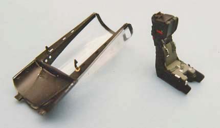
The new resin seat has two cushions to suit the US or Canadian forces and deserves careful painting before inserting. The canopy framing provided in brass looks quite good when added, including the mirrors and grab handles, so I’ve left the canopy open to show it all off. One final touch of gloss varnish over the strip lights and the model was complete.
Summary
Hasegawa's big Hornet kit was always quite good, but the addition of this set has is made excellent and must surely make it worth digging out of the loft! Well done Paragon, this is the easiest and most user friendly after-market set that I have ever used - I thoroughly recommend it!
Availability
Paragon' resin update for the Hornet (set 3203) is available from Hannants, Harbour road, Oulton Broad, Lowestoft, Suffolk NR32 3LZ England.
| Last
Page |
Airbase |
What's New |
Home |
Reviews |
Next Page |