Academy
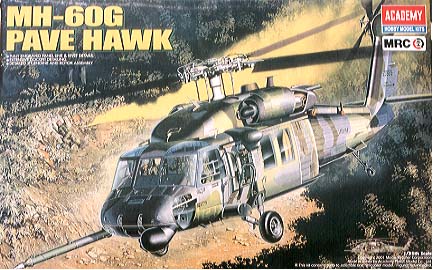
MH-60G
USAF Pave Hawk
Kit No. 2201. 1:35th scale
Academy
MH-60G
USAF Pave Hawk
Kit No. 2201. 1:35th scale
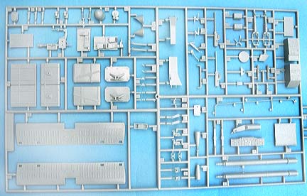
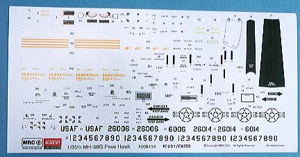
All the frames are moulded in a light grey plastic with no flash what so ever and the clear parts are perfect, the decal sheet reflects the nature of the beast with all low viz black markings, there are some yellow stripes for the rotors and thankfully Academy has thought to back these items up with a separate white backing. The instruction booklet is very comprehensive and construction should not be a problem for anyone.
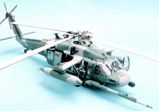
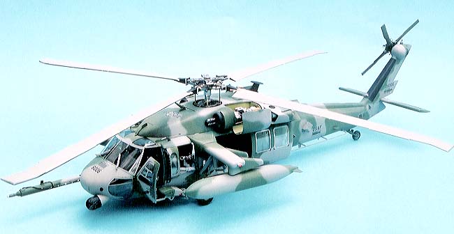
The MH-60G is the aircraft the USAF uses for Special Operations support. Similar to the HH-60G with in flight refuelling and radar but the MH has night and all weather capabilities and has a FLIR turret also, the other standard feature is the provision for external stores pylons (ESSS), it also has a folding stabilators hence the new parts in the kit. It seems that the USAF operate sixteen of these plus another 82 HH-60Gs in the combat rescue role.
Construction notes
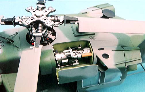
Step 1 the rotor hub assembly, take care when adding parts B56 they will not go at the angle shown and if they did then parts D31 (the blade damper) would not fit. In fact the whole piece is at the wrong angle as shown in a close up photo in Sqadron Signal’s "Walk Around" book.
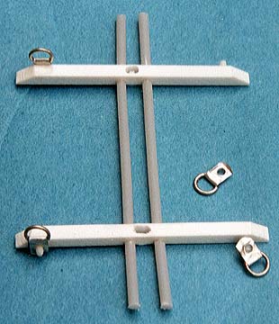
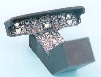
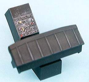
Step 3 the cabin ceiling part A3 is a little bare in this version and so I decided to add some extra detail, I built the seat attachment bars from strip and rod from the Plastruct fineline range and to these I added the “Fast Rope” rings made from a bit of thick silver foil and some telephone wire. The wire was wrapped several times around a suitable size piece of rod, slid off the end and snipped with a pair of scissors to form individual rings. These items are painted red and are used for those guys to hook their abseil ropes into as seen in “Black Hawk Down”.
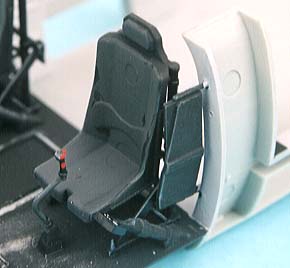
Step 4 the pilots seats are very bare and some seat belts need making, I used strips of foil from the wrappers on scalpel blades plus buckles from a Reheat set of 1:32nd seat belt set.
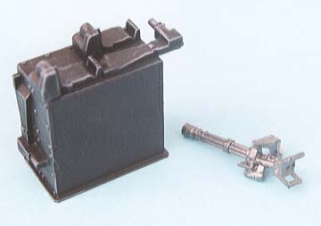
Step 7 before adding anything to the cabin floor I sanded down the box around the cargo hook bay until the floor sat in the body nice and level but remember to re establish the slots for the hook itself. I made some additions to the underside of the cockpit floor, there is lots of space there, and you can see from one side to the other through the front windows so you need some panels to fill out the void. Using 30thou plasticard I added two strips under each side around edge of the step in the floor. When these were hard I drew a rough pencil mark on them following the line of the fuselage then cut and sanded back until the floor fitted nicely into the front of the fuselage, these were then given a few lightening holes to enhance the appearance.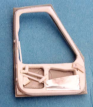
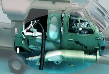
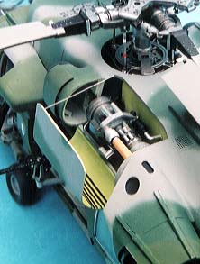
It was then that I discovered that there is a lot more to the door than just the outer shell. A good close up photo revealed all the details so I started with a sheet of 80 thou card cut roughly to the shape of the door, the window and panel shapes were then drawn on in pencil and drilled and cut out then cleaned up. This left me with a fairly pliable frame that I could bend to the curvature of the door, next I sanded the outer edges to match those of the interior lines and this was finally scraped with a knife blade until the correct shape was acquired. Once cemented to the door the framework had various rods and handles fitted plus the map pocket was made from thick foil and superglued in place. The exterior hinges were removed and new scraps of card added to make a better joint to the fuselage when finally mounted. The exterior door handles were sliced off and remounted in the horizontal position as seems to be the norm.Step 11 note the new panels for the intakes, these are quite delicate so take care.
Step 12 it is important not to get the HIRSS assemblies mixed up, they are handed but they will go in on the wrong side and look odd.
Step 13 deals with a number of items, again don’t fit the cable cutters to the legs until you have the wheels on, they WILL break off during construction. The starboard sponson which houses the IFR probe needs a step for the drivers to climb in with, I used the tread plate cut from the spare part A15 and added it to an “L” shaped bracket cut from 30thou card.
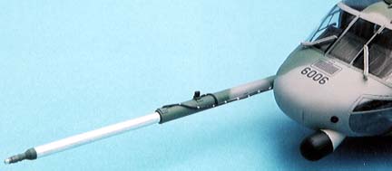
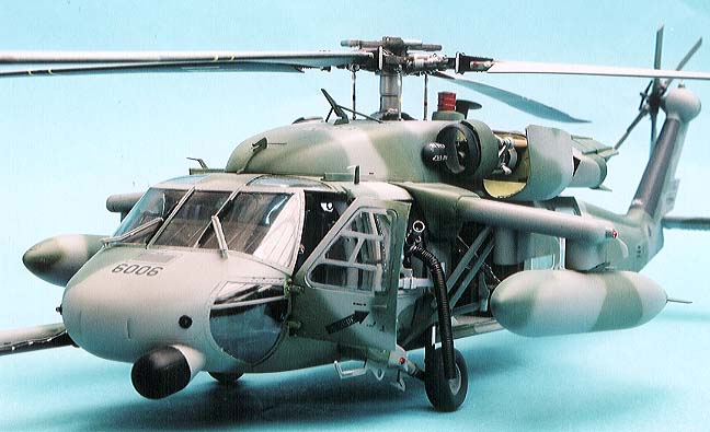
Next item was the IFR probe, although nicely moulded; it lacks some details so I decided to replace the whole thing with aluminium tubing. First I cut the detailed nozzle from the kit part and put it to one side, and then I selected the correct size tube to match the kit pipe plus two sizes down (these all fit inside each other). The largest was cut to the length of the kit part and two 3mm rings cut from the next size down, the smallest tube was cut to 83mm long and one of the rings was superglued onto one end of it, the
opposite end had a plug of suitable sized tight fitting sprue inserted to provide a key for the nozzle to be cemented to and left to harden. The other ring was glued flush into one end of the large tube to act as a stop and the smaller tube was inserted from the other end and pushed right through to the stops. Again as tight fitting piece of sprue was selected to insert at the rear end of the large pipe,
but first the extendable pipe was pushed right back to it’s closed position and the plug was then inserted to meet it to act as the stop (you could loose it otherwise) leaving appx 10-15mm outside to glue into the sponson and hold it all level. A new bracket will have to be made to replace part G29 but that is just a plastic ring and two stays, easy peasy. Add the wiring and tiny blocks of scrap plastic and there you have a working IFR
Step 14 add parts B12/13 but don’t add the HIRSS units until after painting is done.
Step 16 parts D21 are best mounted with the bottom of the L shaped angle facing inboard, not as shown, they will then fit the cover part B52 a lot better.
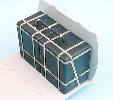
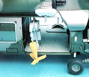
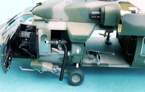
The remainder of the construction is straightforward giving you a choice of configurations,I built both rescue hoists and all the guns and mounts but they were not all used, I did pose some for photos but these were only fixed in with PVA which is easy to break away later. I also wanted to use the spare ESSS pylons from the Black Hawk kit so these were assembled and added after painting (it was a lot easier)
The kit miniguns, which are fully adjustable, lack the shell ejection chute as seen in many photos so I made them up from bare telephone wire tightly coiled around a 2.3mm drill bit appx 40mm long, When this was slipped off it was bent to shape and coated in PVA glue and left to set, this formed a nice covering to paint black. One end of the coil had a small length, 2mm, straightened out and inserted in a tiny hole drilled in the gun, quite effective I thought.Painting and decals I have used the camouflage drawings provided in the instruction sheet which aren’t perfect (some bits do not join up) but I understand that the choppers are now painted overall dark grey but you will have to find your own reference for that.
The cockpit glass areas were masked using Sellotape (scotch tape) but I left the glass parts out of the cabin doors and gunners windows, which were masked from the inside with ordinary masking tape to shield the interiors. These were then held loosely in position with Blu Tack or PVA glue, as was the engine compartment's cover while I sprayed the camouflage on, this made it easy to get the patterns all matching on the moveable parts. I sprayed the light grey all over first and the using a soft pencil I drew out the patterns as needed and followed up spraying the colours freehand along those lines. The colours are all listed with FS number references which you can find in your favourite makers ranges, I have used Humbrol paints on my model simply because they are hard wearing and quick drying.
When all was dry I removed all those moveable parts and touched in any bare areas then the whole model had a couple of fine coats of Klear (Future) dusted on and then a single thicker coat ready for decalling. Once the decals were on another coat of Klear, to seal them in was added and finally a coat of Klear mixed with some Tamiya Flat base, in 3 to1 proportions, was sprayed on lightly to bring the finish back to a nice sheen. All the sub assemblies can now be added to your choice but I had a problem with the cabin ceiling, in this and the black hawk kit, with regards to mounting the rotor base part B59. Although I double-checked the location of the floor in the fuselage sides it still left the locating ring for the rotor base too far aft and it fouled the roof when mounted. The only solution was to cut away the ring and mount the base in the centre of the roof aperture, remembering to keep the forward slope on the base sloping forward, this is only a tiny movement so don’t go overboard on it. The rotor blades are a tight fit into the hub so I have not cemented mine and they can be stowed away for transportation.
I think that covers everything, now, my opinion? Well it provided hours of enjoyment with virtually no hassles and I have an excellent model at the end of it. All the parts fitted without problems and there is no filler anywhere, value for money? Certainly.
Last Page
Airbase
What's New
Home
Reviews
Next Page