
Revell
Tornado RAF. 31 Sqdn Gr.Mk1
Paragon slats and flaps set
Kit No. 04705. 1:32nd scale
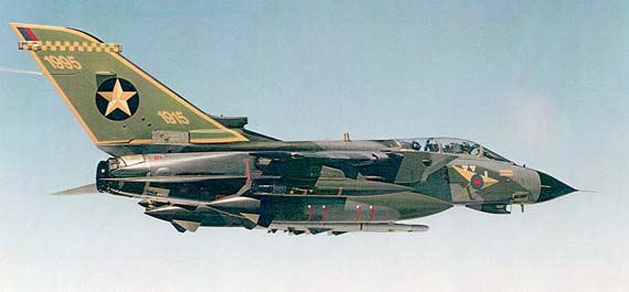
As a logical follow on from the Luftwaffe IDS model released last year Revell have just released the RAF version of the Tornado, you get the full IDS kit some of which you don’t use plus a whole new parts frame with RAF stores consisting of Hindenberg fuel tanks, two nice LGB’s, four 1000lb British bombs, a sky shadow pod plus RAF fairings for the fuselage pylons. All the parts are, like the rest of the kit, crisply moulded in light grey plastic, panel lines are all engraved and the cockpit is pretty well detailed but the seats are a little basic. The clear frame with it’s landing, navigation and anti collision lights plus the huge canopy is crystal clear, so well detailed is this kit there is even detailing on the inside of the canopy making it easy to paint the interior (you can’t use the old trick of painting the interior from the outside, as the inner bits are different and they show up when finished).
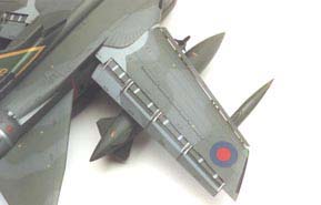
The decal sheet is enormous with markings for two green/grey aircraft of 31 and 617 Sqdns and a gulf war machine namely “MIG EATER” every bit of stencilling is provided although a bit of silvering may occur with these tiny items but you can get over that with a tiny dab of KLEAR under each one. On the whole the model looks pretty accurate and makes a nice Tornado but being pedantic or nit picking if you like I can’t help feeling there is a problem of distance at the rear fuselage, the leading edge of the tailplane seems a little too close to the wing seals making the adjustment markings up tight instead of a little behind but we are talking millimetres here (see photo 1)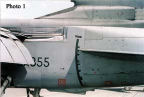
At the same time as the kit arrived for review Paragon supplied a whole bunch of resin extras for use with this kit the first was the flaps and slats set then came the JP 233s and a set of Hindenberger tanks (useful if you only have the IDS kit) next was an access ladder but to crown them all was a beautiful pair of Martin Baker Mk 10 seats fully decked out with straps and fittings.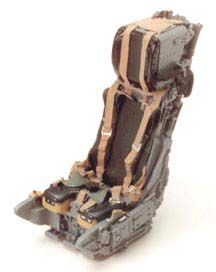
At the same time I received the EDUARD brass set for the IDS and although slightly different to the RAF it was used to enhance the cockpit mainly, I will deal with the kit construction first and come back to these.
Construction notes
Step 2 make sure you get part 8 up the right way note the pins below should match the floorpan.
Step 9 The two fuselage halves are a butt joint so I inserted a strip of 40thou plasticard app. 20mm wide along the inside of the seam, extending it 5mm out the back to form a lip for the rear fuselage to locate against.
Step10 I left part 19 until later for easy painting and masking.
Step 13 Part 27 is part of the nose cone (part 28)not the section that swings out with the radar on it.
Steps 15/16 I prefer to leave the pylons until later as it is difficult to paint with them in position but you do have to cement them in later. You will note that pylons have a small extension on the top at the front, this is a small movable fillet that moves up and down as the wings rotate if you are going to show them swept you will need to cut them off. (See fig 1)
Step 20 the retaining bar part 47 will easily snap the pins on the tailplanes so I removed the mountings on them and drilled a hole in each and pushed a length of 20 SWG aluminium tube through the fuselage, cut it to length and popped the tailplanes on each end.
Step 21 The edges of the fuselage are again butt joined and I added some strips of 40 plasticard along the inside edges to act as locations and give strength (see photo 2)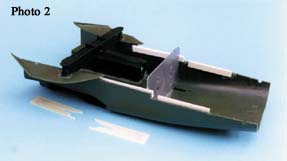
Step 22 If you modified the tailplanes there is no need to add them here but do make sure that your joints are strong particularly those shoulder joins as the weight of the wings can easily part this seam.
Steps24/25 Most of these parts are engine related and as such should be bare metal I have used Rub n’ buff and ‘Zebright’ black grate polish to achieve the burnt metal look, but with the advent of Alclad II of course you can improve upon that, the whole unit was not added until all the painting was finished to avoid masking, it is a good fit and should cause no problems if you use a mild cement like Slaters MEKPAK. One final point Revell have made part 62/63 from the same master expecting you to roll 62 over to fit in the location provided in part 61 this is wrong , 62 should be in the same attitude as 63 which is correct, as you can guess manufacturers of real aeroplanes do not turn engines upside down to fit on the opposite side they just move them across.
Next step! After cleaning up the fuselage joint I added the fin ensuring that the join is good and well seated.
Step 41 Use part 90b on the port side not 92b or the angle will be wrong.
Step 61 The fuselage pylons are still those for the Luftwaffe but the RAF use the MACE (minimum area crutchless ejector) system so I use some thick plasticard strip to fill all the locations for the steadies, if you want to load the bombs use 1.25mm rod as locators.
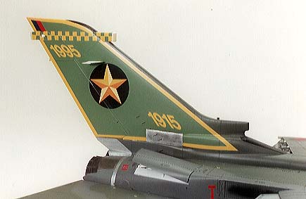
Step 80 The decals on the starboard fin are shown wrongly positioned, 1915 should be at the base of the fin each side and 1995 at the top. The position of decals 24/27 are also transposed, they are shaped this way to allow for the undercut of the rudder so swap them over to the opposite side.
Slats and flaps etc. etc. Paragon, always try to provide parts to bring a bit of life to a model and slats and flaps will make a model stand out from the crowd so here we go, when removing the required areas from the wing do the upper half first, check with the resin flaps that the bits remaining line up with the tracks, then tape the halves together and line up part 22 with the inner edge of the upper wing flap, now mark out the extra area to be cut out from the lower wing inner edge. The rear edges of the cut out from each flap was scraped away from the inside to give the impression of a thin sheet of metal as on the real thing, taking care not to damage the runners on the top half. Assemble the wing halves and leave them to harden.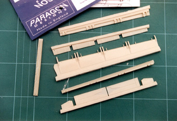
Slats and flaps are from Paragon
As I wanted to take the wings out for Transportation I cut a slot into the pivot hole narrowing it at the edge of the hole so it would click into position and I removed the rear of the engaging teeth as shown in (photo3) to clear the new wing seals
I inserted the leading edge interior first to add some firmness to the structure then proceeded with the flap runners parts 15/16/17, I found these needed a little packing on the “step” to keep the wing halves at the correct depth they also needed shortening at the front edge by app 3mm or they run into the ridge along the inside of the wing, (see Fig.2)at the same time refer to the track runners on the flaps to get a good alignment, this is most important as the wing will bend if you don’t, a little extra care here makes all the difference. 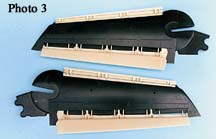
Take care when making up the flaps as it is possible to fit parts 7-14 upside down, cut them off carefully, file the two slots ready for the screw jacks then ensure that the two long bands on the surface are on top. I would suggest that you refrain from fitting the flaps permanently until after painting and decalling, and when you do, make sure you have the pylon and aim-9s in position or you could have a foul up.
The wing seals parts 20/21 are about 2mm too long to fit into the kit recess and as mentioned earlier you can’t extend it rearwards so I simply cut the front end opening on the seals, exactly the same but 2mm further back, using a piece of stiff card cut to shape and moved back scoring a new outline on the resin to cut to. The seals fit flush in the fuselage so trim a sliver off the top surface edges (part 54) and deepen the cut outs in part 48 by a mm or so.
The assembly of the fuselage is as per kit instructions with parts 37b/c wing anchor points fitted so that the wings will slip in later, when it comes to adding the flaps set the angle you require then add the screw jacks cut to a suitable length don’t do it earlier as you may well get the angle on these wrong. The JP 233s are a simple assembly and again I used 1.25mm rod to mount them on the pylons before attaching them to the fuselage. When you make up the ladder you will note that there is little to brace up the platform and in fact the real thing does have another brace from the legs to the platform (see fig 3). The cockpit in the kit is quite good with raised details on the panel but Eduard has come up with a brass etched sheet to improve the kit as a whole with lots of new instrument panels, seat straps etc I have not used all of them but those I did, all fit well. There is a ladder included which is nicely done but it is flat not 3D like the real thing, also included are some small open panels, additions to the air brake wells and new fins for missiles and fuel tanks, nicely done and all quite useful in this scale.The cockpit with Paragon seats and Eduard etched brass details set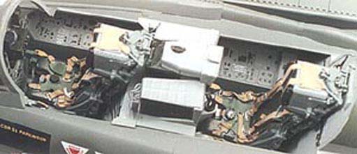
The two seats from Paragon are two of the nicest I have seen and if you buy nothing else at least treat yourself to these I think you will be impressed also.This project took me some time to complete and I must say I enjoyed every minute of it, you certainly get your moneys worth with this kit and though the “add on” aftermarket bits are expensive they certainly make a difference oh! And don’t forget there is a new xtradecal sheet out for this model, sheet No X00432. The Paragon parts are available from Hannants as is the Eduard etched brass set.
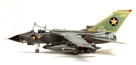
Port view
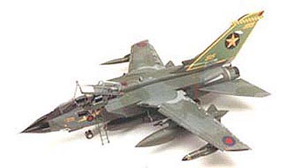
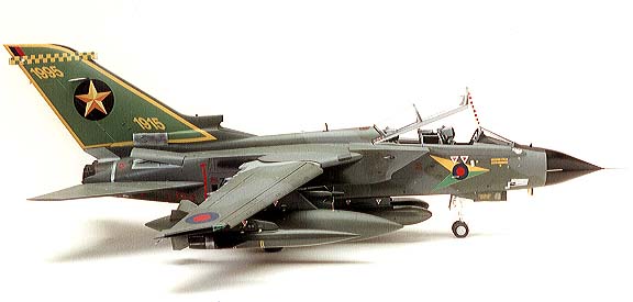
Starboard view
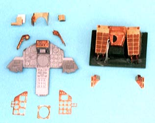
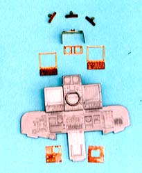
Eduard front and rear cockpit brass parts
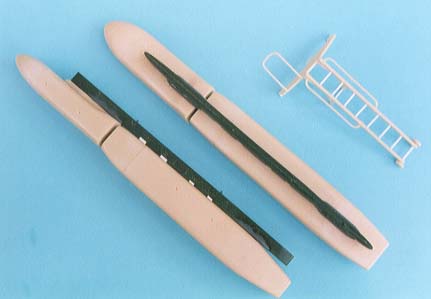
the JP-233s and boarding ladder
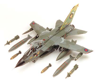
with the stores from the kit also