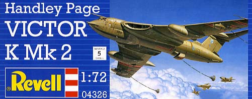
Matchbox/Revell
Handley Page Victor
K2 Tanker
Kit No. 04326. 1:72nd scale
Matchbox/Revell
Handley Page Victor
K2 Tanker
Kit No. 04326. 1:72nd scale
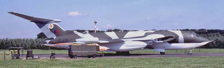
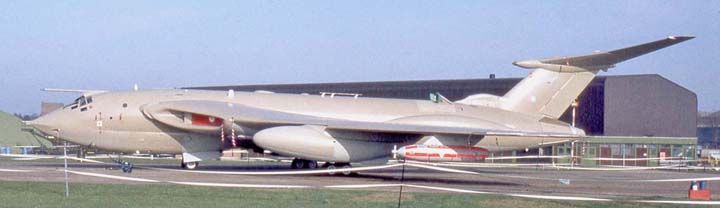
This aeroplane has been a favourite of mine for many years and when I was given the job of designing the instruction sheets for the Matchbox kit I was in modeller’s heaven.
First I had to learn how to put the kit together and then work out how to show the modellers where it all went and by the end I had built several kits, not painted but made up none the less,
I built two specials up in the markings of 55 & 57 Sqdns and cased them up; we then presented these to the two Sqdns at Marham and these are now in their memorabilia stores I expect.
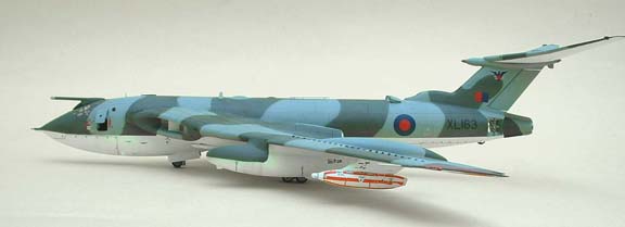
I then had to build six copies for various toy fairs and eventually built one for me which I still have but then I thought I would like to build a super detailed model and so I set about rescribing all the panel lines, an awful boring job, and half way through I was side tracked with the latest release of somebody’s kit and it was forgotten until a couple of months ago when I opened a box only to find a part done victor kit that I had started 20 yrs earlier.Well that inspired me and when the new sheet of decals for Victors came out from Euro Decals I just had to get started again, by now Revell had released their copy and I acquired one plus the Flightpath upgrade set to start afresh with on a second model.
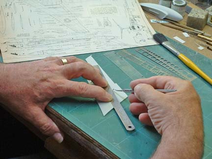
The first thing when the major parts are removed is to engrave the panel lines, we all have our own way of doing this but I used the originals as guides by scribing along each raised line and when all are completed I rub down the surface to remove the raised ones. This fills the lines with dust which is a useful way of checking for errors, if all is OK then a stiff brush will clean them out.
Some might want to leave the raised ones alone but with the wing sections you will see they are all parallel this was because the tool makers traced the edges of the panels rather than the gap between, so it won't look right if you leave them.
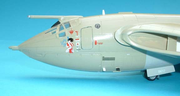
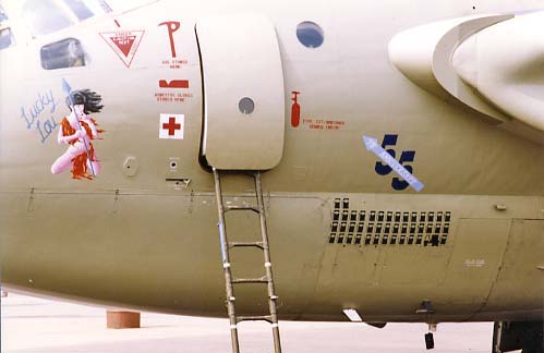
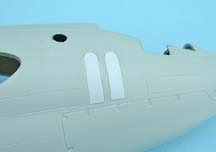
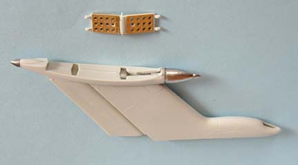
When scribing the fuselage remember that there is no crew door on the stbd side but around that area are two stiffening strips which I made from 5 thou card see photo.
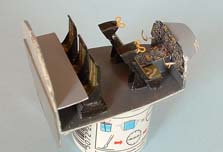
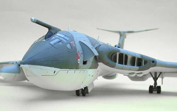
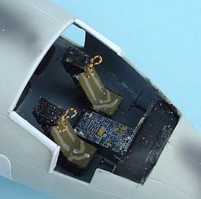
 I built the cockpit area up and added a navigators table on the rear wall just above seat level plus the brass details from Flightpath, I used the kit seats and painted the seat straps, it seemed a waste of money to get after market seats which will be mostly hidden. I added a plasticard extension to the rear wall below the cockpit floor, this was to retain the nose weights which I fixed in with epoxy resin after the cockpit had been painted and added to one fuselage half. The two windows behind the crew door are round not oval so the holes were rounded out with a drill bit, new windows were later made with Kristal Kleer. I decided to have the centre hose reel lowered and this was built up with the etched brass parts and one of the baskets just tucked inside ready to be added when the fuselage halves are assembled.
The main Construction started with the wing outer panels, before cementing clean up the holes for the aileron hinges, makes assembly a little easier. On the Stbd side thin down the lip around the aileron area or the wing will be too thick for the part and the trailing edge of the aileron itself needs thinning to match the port side.
Now that the paint was dry the fuselage halves were cemented together and taped up as were the fin and tailplane halves these were then left to harden overnight.
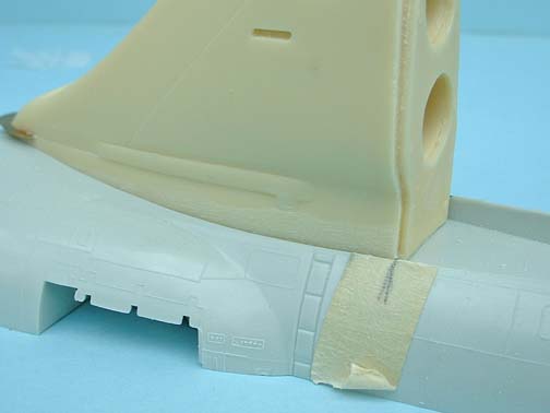
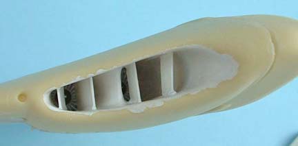
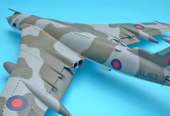
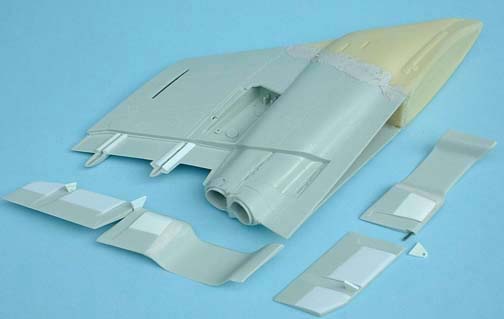
Time to fit the resin intakes to the inner wing, my parts needed a lot of adjusting, firstly they wouldn't fit into the recess in the fuselage for the wings, the two pieces are not the same size inside the intakes and none of the brass vanes fitted at all I had to make new ones from plasticard and each side was a different shape and size, I had to sand the resin to fit into the recess first making sure it fitted snugly at the leading edge. Once these were correct each was placed in the recess and the rear edges of the resin marked off with pencil as a guide for cutting the inner wing parts which were taped together and placed in the recess to be marked off also. My cuts were made a fraction from the line and gently sanded back until both the resin and plastic fitted the recess precisely then they were superglued together.
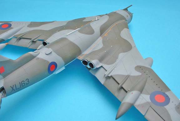
Outer wing panels can now be added but leave the pitot tubes off till much later, they break easily, I cut the reinforcing strips from 10 thou card and added these, sizes for them were taken from Arthur Bentley's drawings in Scale Models Magazine (Nov 1983). The vortex generators are a bit crude so Flightpath have provided brass replacements, these are tiny and you only get one spare so keep track of them. I sliced off each tiny plastic bar and drilled a 0.3mm hole in the centre of the original position; the area was then sanded smooth before popping each tiny brass part into the holes with a dab of superglue.
The tail cone can be made up with open or closed airbrakes and I made one of each, for the closed version I cut the strakes from the top and bottom of each door and cemented it closed, it is not a good fit and needed a fair amount of packing and filler. When finally smoothed over new strakes were cut from 10thou card to the original pattern and cemented in position.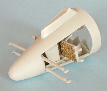
For the open one I used the etched brass parts but not as instructed, the “wings” on kit part 33 were thinned down considerably and the brass parts 47 / 50 were added to the front and back of the “wings”. When all had hardened I reamered out the lightening holes with a round file so the plastic corresponded with the brass. Parts 35 and 36 were added to this and it was placed not cemented along with parts 32 between the tail cone halves which was then cemented to the fuselage, the doors were not added until the end of construction.
The tail fin and planes can now be assembled and if you have the set add the new metal fairings to the fin bullet, the underwing tanks and hose reel pods plus the undercarriage bogeys, with wheels only and if you have the set the nice brass centres for the wheels, can also be made up.
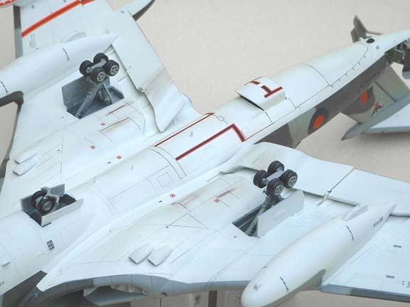
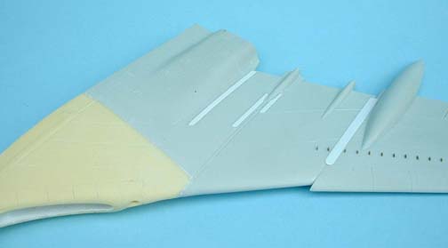
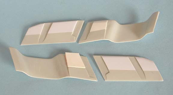
While all these parts hardened off I turned my attention to the flaps. I wanted one set deployed but the plastic is moulded so they can be closed and they need further treatment. There is no step on the real flap so I added 40thou card sections to the inner edges (See Photo) and sanded these to the correct shape, the runners on the wing underside are formed from strip plasticard and a triangular hinge plate was cut to size and drilled out to take a small length of flower wire, this in turn was inserted in the midsection between the two flaps. Later when the flaps were fitted the hinge was cemented into the centre runner and a tiny strip of card added to each of the other runners and the angle of the flap set on these, remember the inner flap will droop slightly more than the outer flap.
If you have cleaned up your fuselage joins now is the time to add the wings and fin but take care here to get the wings level and the fin upright then leave overnight to harden. Filler will be needed around the wing joint and the base of the fin but only small amounts, I ran a couple of lines of PVA glue along each joint and that worked fine for me.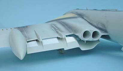
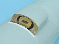
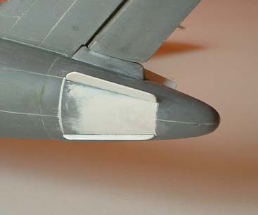
You can show the RAT intakes open but they need to be placed higher than shown on the instruction sheet, slightly wider apart than the base of the fin but level with the grilles for the exhaust air which are along side the fin base. Etched brass grilles are provided with the set and should be level with the surface so I used a dentist’s burr to make a small recess the shape of the grille which was then glued in with PVA glue, white metal intakes are provided but my samples were badly cast with the top “lip” hardly there at all so I used the kit parts (note the rounded off rear edges), of course if you want them closed just leave them off but you could scribe their outline into the plastic.
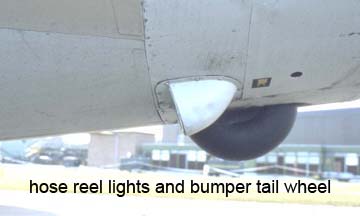
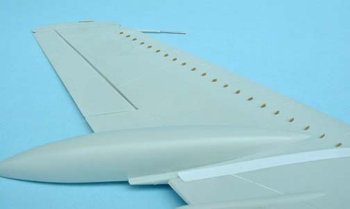
The tail wheel (yes there is one) is poorly depicted so I removed the “bump” and cut the edge off an old wheel I found in the spares box to mount in it’s place then while in this area I added the lights that illuminate the centre hose reel, one either side of the wheel, from some square rod sanded to shape (see photo), there was also an Omega aerial on XL160 but I am not sure if it is on all aircraft.
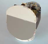
The canopy provided in the kit has never fitted perfectly and the only answer is to add some thin plasticard strip around the opening until the “glass” fits nicely, then sand down the card edges till level. I have used two methods to overcome this, on my old kit I had sanded all the detail off the glass and polished it to a smooth surface flush with the fuselage, now the Flightpath set gives you a brass frame for that area but that has to be curved around a compound curve and it won't work here so I used it as a pattern to cut a 5 thou plasticard frame which can be carefully cemented and will conform to the shape of the glass. On the other I packed out the gaps and added the glass but before sanding level I masked the windows to avoid any damage, both worked well. The bomb aimers windows need a little sanding to fit and you only need to mask them if you want them open/clear, I covered the nose windows with plasticard and painted them, why you ask, well when I spoke to the station commander at Marham I asked why the windows were plated over and his reply was "we ran out of glass replacement parts so we blocked them off with metal plates". The brass set provides two options, just a framework or plated windows.
The crew entry door can be displayed open but the side panels are much too thick so I chopped them off and replaced them with some 15 thou card cut to the pattern of the originals. Add the wing tanks now but leave the hose pods until you put the decals on, it’s much easier.
Make up the main undercarriage legs and add the brass parts if you have the set, mount them in the bays but don’t add the bogies yet, leave them until later when all the painting and decaling are finished, reason, the joint is fragile and will easily break, I reinforce mine with a flower wire rod between leg and bogie plus some epoxy resin but most of all you want the bogie to be level so when you fix them leave them standing overnight on a flat surface.
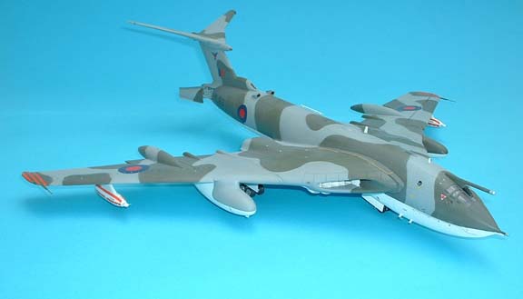
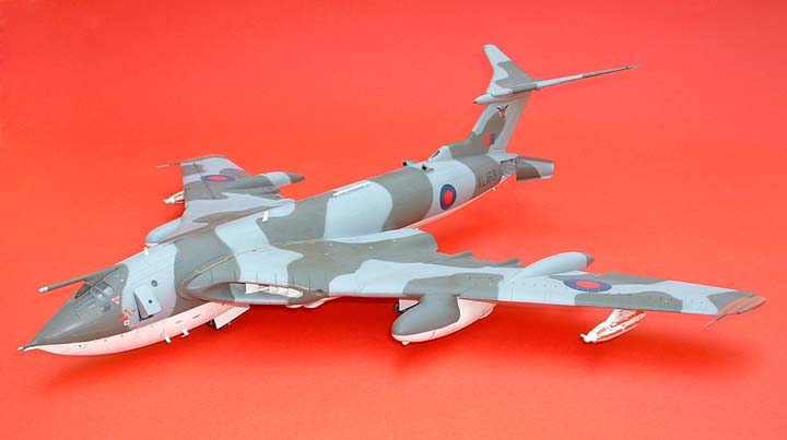
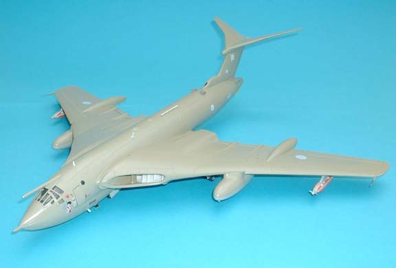
I now added the flaps and all the tiny aerials along the fuselage, the pitot tubes had the front portion cut off and the thicker part was drilled out to take hypodermic tubes and then glued to the wing tip, a touch of filler is needed here. The refuelling probe was mounted over the cockpit area plus the windows and intakes were masked up ready for painting. The colours I used were Humbrol 163 green, 165 grey and 130 white for the underside.
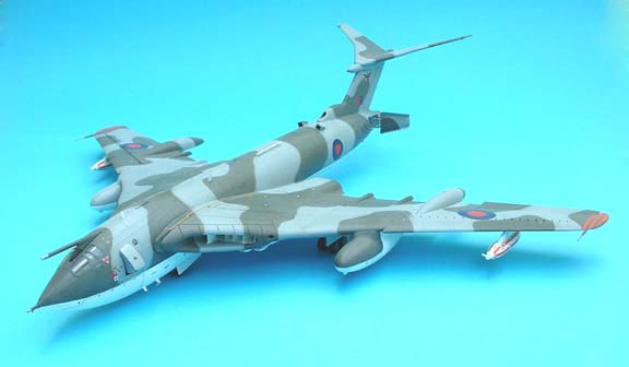
After first spraying the joins with a matt dk grey to check for blemishes I sprayed an all over coat of grey then lightly pencilled in the outlines of the green areas and with the airbrush almost closed I followed these around to outline the areas which were then filled with the airbrush opened a little more. As I wanted sharp demarcations I used a 1/8th ins flat brush dipped in the paint I had just sprayed to run around the edges (don’t use paint from the tin as it is much too thick and will show up) this is easier and quicker than masking the pattern. Left for a day the paint is hard enough to mask up for the underside spray, I use Tamiya’s masking tape which won't lift the paint below, when the masking was removed from the intakes I used a flat brush again to paint camouflage on the lips. I used a similar method to paint the hemp version using Humbrol 168 hemp and 166 Lt aircraft grey.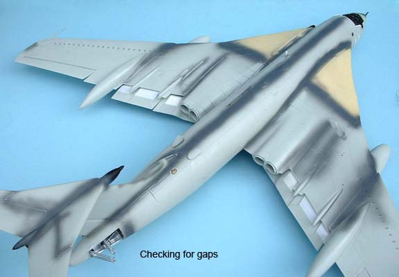
Next came the Klear (Future) coats a light dusting first to provide a key then a heavier coat to get a nice gloss finish ready for the decals. When they were on, another coat then a matting coat, a mix of 3 parts Klear and 1 part Tamiya flat base X21. This needs only to be dusted on to your liking, too heavy and it will be much too matte
Unmasking time now and any detail painting needed such as Nav lights etc. etc. add those bogies, doors and pods and you should have a model to be proud of.
Ted Taylor Aug 2004