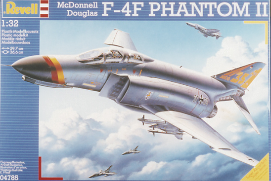
Revell
F-4F Phantom II
Kit No. 04785. 1:32nd scale
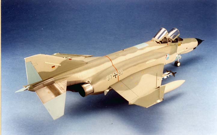
Revell are to be commended for making such a big kit for such a reasonable price and of a very popular subject the F-4F/E, this kit is an adaptation of the first RF-4E model with three new sprue frames containing new front fuselage halves, instrument panels, slatted outer wing panels and two much improved seats. The decal sheet is enormous with markings for four aircraft (despite the box top blurb) one of which is for the 35th anniversary of JG 35 with its colourful fin and nose markings. The mouldings are all in light Grey plastic with absolutely no flash, the canopies are as clear as a bell and their fit is near perfect. Surface detailing is superb, all engraved with excellent fine lines to just the right depth and width for my liking, they disappear from a little distance, the cockpit has separate consoles and instrument panels all moulded with raised dials, switches and knobs which look to be correct for the "F" variant and stand out very well when dry brushed. Two sets of missiles are provided, sidewinders and AIM-120 AMRAAM's which mean that the aircraft depicted must be part of the upgrade ICE (Improved Combat Efficiency) program as these are the first Luftwaffe machines to carry such armament, the program also includes a radar upgrade and if you care to leave the nose cone open on your model a nice improvable radar set can be displayed, although I can't understand why they chose to mould a part of the nose cone on the fuselage halves. Wheels come in two sets with or without flattened tyres, there are optional positions for the airbrakes and there is a standard 600 gal tank as well as the later F-15 type belly tank which is seen on most aircraft these days.
Since reviewing the RF-4 kit in July '95 SMI. I have modified my opinion a little as the fit of the parts is, for the most part, very good but there some problem areas which will need a little care though but more of that anon. Instruction sheets are not one of Revell's strong points, you will find a few mistakes here and there but the biggest problems occur on the camouflage plans where the tones used are not easily distinguished and some are wrongly labeled in the key boxes, once again I referred to the "never ending story" that appeared in Scale Models International. Nov. '93.Step 2 The new seats are much better but need a little reworking i.e. the parachute pack (parts 175-176) has sharpish angles on it's edges ,round these off by scraping with an old blade then remove the moulded straps as I feel sure you will want to make your own, I did using foil from a wine bottle and some 1/32nd Reheat buckles . Construction Notes
Step 3, side consoles (parts 183-185) before mounting adjust the holes for the throttles (11-14) as the locators aren't compatible.
Step 4, the drivers control column (part 10) is still depicted the wrong way round, turn it through 180 degrees.
Step 5, the Wizzo's panel (part 187) will not locate properly so remove the pins.
Step 6, seats are best fitted later as the cockpit floor is a bit lower than it should be and packing is needed beneath each seat to bring them up above the cockpit sill, I had to use two bits of 80 thou card in the rear.
Step 8, I have already mentioned that the cockpit is much too low but not much can be done without major surgery to the panels etc. the thing to note here is not to make the fuselage too narrow by squeezing the centre bar across the cockpit to meet in the middle as the canopy bridge may not fit without alteration, use this as a guide.
Step 13, use some imagination to paint the turbines try some contrasting metallic paints.
Step 14, before joining the fuselage halves, cut away the small plates at the foot of the fin intake, these can be replaced later with 15 thou card. It is here I have revised my thinking, fit the turbine wall to both sides of the fuselage and make good the join at the bottom
Step 15, part 58 has a cut out to take the nose section part 203, I found it expedient to cement some strips of 60 thou card around the cut out to make sure 203 locates exactly, while in this area I decided to open up the two doors either side of the tank pylon, I cut away the moulded doors and replaced them in the open position using 15 thou card slightly rolled around a brush handle this is characteristic of any phantom standing still, at the same time cement four bits of scrap plasticard over the holes where the missile fins protrude, you will see why later.
Step 16, do not fit the tailplanes until painting is finished and it is here that the biggest defect in the model occurs, the fin top is too square and has an up hill slope, to cure it I cut the ECM bulge off then removed a section before replacing the bulge (see Fig 1 ) and rounding off the top curve.
Step 17, you might find a gap when fitting the wing to the fuselage , attach some tape to one wing tip then over the fuselage to the other, tighten until the gap is closed cement and leave overnight.
Step 19/22, parts 46/51 the splitter plates have a hollow rear face when it should be solid, I have removed the locating pin and used some 30 thou card plus some scrap bits for packing to fill the void (see Fig 2.). Parts 49 and 54 will not fit the splitter plates if aligned with the fuselage and vice versa so a little filler is required around this area.
Step 30, the landing light is positioned wrongly as is it's window in the door, remove the location and the rivets from the inside of the door, fit the window (part 217) from the inside of the door then add the lamp box (part 219) so that the top light can be seen through the window and the bottom one below the door it's self.
Step 31, the leading edge of gear door (part221) could be scraped away on the inside to give a thinner section after all it is just a sheet of metal.
Step 32, the linkage rods (parts 94) should fit to the door appx. half way up the lamp box not on the end of it as shown but you will have to increase the width of the leg location to get a comfortable fit.
Step 36/41, the linkages (parts 110) will not fit as shown you will need to drill a 1mm hole a little further outboard in the wheel bay, in line with the rivets.
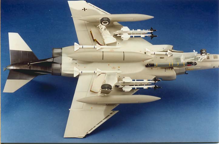
Step 48, AMRAAMs are provided as main armament but they are too long, they are the same length as a sparrow missile, the kit bits will not fit the forward missile bays so I reduced the length by cutting 10mm out of the body in front of the forward wings.
Steps 50/57, ensure that you do not mix up the sway braces (parts 134/137) the leading edges must match that of the wings
Step 58, if the AIM 120 missiles are located in the positions allocated the fins will foul the main flaps so cut off the upper fins on the shortened missile and fill the location holes which you sealed earlier then sand them smooth with wet and dry wrapped around a paint brush handle, the missiles will now fit fully forward in the bays clearing the flaps and the air brakes.
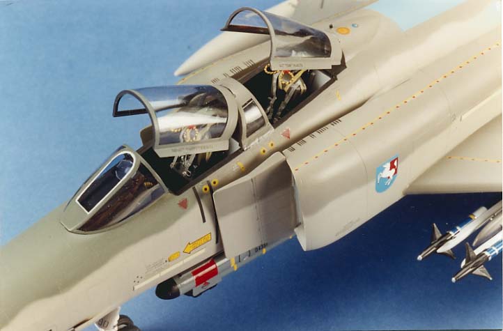
Step 60, fit part 189 directly onto the bridge (part 74) not the control panel as suggested. The canopies can be displayed closed or open but for the latter the hinges are so tiny they wont support the parts the rams are best replaced but even then the leverage is too great so I filed an angle to match the raised frame between the hinge slots on the bridge and rear fairing and a dab of superglue had them well fixed.
Step 62, the crew ladder when made up has no "hooks" at the top to locate it into the cockpit but don't worry as you can not fit it on the model anyway, the splitter plate is too far forward compared with the cockpit, I am not sure what the problem is but something doesn't look quite right just there.
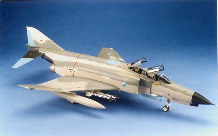
The painting was next on my agenda and while the JG35 scheme was simple the other schemes are hard to follow as the tones laid down are so similar and some on page 16 are incorrect, if you refer to the RAL numbers on page 15 which are correct you can find them all in the Xtracolor range from Hannants these are gloss paints and need no varnishing before applying the decals.
The decal sheet has a number of errors, the worst being the colour of the formation light strips and the fact that all are the same length, those on the fin simply divided into four sections, by the way, those on the fin on JG 35 are painted out not as depicted. The stenciling is good but there is a discrepancy in amounts of some items. This time the section with the panel numbers has English translations making life easier but you'll still need a full day to put them on. With all those tiny decals to put on it is quite easy to get air trapped beneath them and get "silvering"
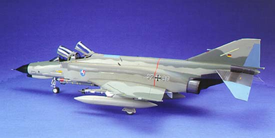
At this stage I always find it convenient to add the U/C legs and wheels ensuring that all the flat surfaces are level, now all the remaining parts are added including the clear parts to finish off the model, as a summary I would say I liked the kit, it has it's drawbacks and inaccuracies but that gives me plenty to do to put it right and I felt quite satisfied with the resulting model, I hope you will tooBig 1/32nd scale
<>This is an improvement on the earlier RF-4C kit , fit of parts is good, instruction sheets are not the best, the seats are better but recommend resin replacements. The tail fin tip needs altering still. The model is painted with Hannants Xtracolor all in proper RAL colours, metal areas are done with Humbrol Polished steel and buffed up then dusted with mat black.