Tamiya
Tamiya's
model produced to
celebrate
30 years in the kit industry
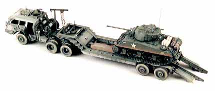
The Dragon
Waggon
US. 40 ton tank
transporter
Kit No. 0000. 1:35th scale
Most people like to celebrate an anniversary and many companies are proud to reach milestone years in continuous production, so Tamiya, having reached 30 years, have produced a special kit to mark this achievement and what a special kit it is.
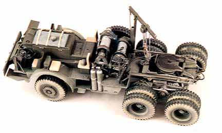
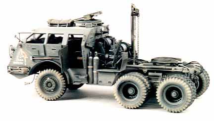
The M25 is a combination unit made up of the M26 tractor and M15 semitrailer, the tractor is a 6X6 vehicle with an armoured cab (later versions had soft tops) and is capable of operating as a wrecker truck in it’s own right with an “A” frame and dual winches at the rear and a single winch on the front. The Pacific Car and foundry Company of Seattle built the trucks for use in the European theatre, all the wheels are driven but the twins at the rear are chain driven, there is a crew of seven and the roof has a ring mount M49 for a .50 cal machine gun for AA protection
this alone took four days to assemble all the components
without painting.
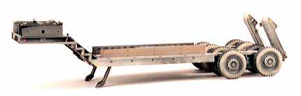
The trailer is a step frame flatbed and has eight wheels mounted in singles on two bogies, all fully articulated, these can be adjusted closer or further apart to accommodate vehicles of different widths. Hinged ramps at the rear are used for loading and various guides are used to protect the tyres and keep the tank in line when being winched aboard.
The kit contains some 600 parts and faithfully reproduces all the features mentioned above, all the parts are finely detailed and I never found an ill-fitting part anywhere. There is an etched metal sheet for various steps and the exhaust shield plus metal hinges for the rear ramps, one also gets wire rod and chains to complete the ensemble. The decal sheet covers three vehicles and all are basic olive drab, while the instruction booklet, 28 pages of it, is very comprehensive.
My construction notes
There are 20 sprue frames in the kit and you are required to cut parts from various frames at any one time, so I would suggest that you wrap a piece of masking tape around each frame and write the frame letter on it in red so it can easily be identified as you work through. There are lots of gates on each part (so that each part forms perfectly) and each of these attachment points needs careful cleaning up or the parts will not fit flush.
Step 2. I liked the way the chassis is built up, with clever moulding, into a strong frame and even though parts B2 and 3 look similar, you can’t put them in the wrong place as the pegs are different, that’s important in such a complex kit as this. I also liked the way the road springs are moulded in two pieces for if moulded in one lump there will be shrinkage, just shows how much care Tamiya take.
Step 4. the steering arms (part C29) are a little false, they do not end at the road spring really, in fact the drag link is connected to part C6 in step 5. If you drill out each joint with a 1mm drill bit and add rivets from 1mm rod you can have a working set-up just like the real thing.
the winch is highly detailed and the cable drums
actualy turn this realy is the business
Step 5. take great care with the cement here or your steering will not work at all I also recommend that you only remove one set of stub axles at a time as the parts are so similar and could be confused, once you get them right they will only fit on the correct end of the axle.
Step 6. Parts H30/31 are the brake cylinders so if you want to add air lines to them now is the time to drill the holes in the centre of the tops to take the pipes later on. There are a number of different size ‘poly caps’ in the box, make sure you use the ones on the frame not those in the packet when you assemble the differential.
Step 8. Add the drive train to the chassis before adding parts B10 or the propshaft will foul it.
Step 9. The tyres are rubber and nicely moulded but there is a centre seam to get rid of, I used a rough sanding block on each tyre before adding it to a wheel it gives a nice scuffed look as though the tyre has been used.
Step 13/14. the windows were left out until after the interior was sprayed as were the smaller items like canteens and fire extinguishers. Take care also when you position the cab as the hand brake can easily get caught and snap off, place your thumb over it while lowering the cab shell.
Step 16. When fitting the armoured side windows make sure the hinges fit above the plates moulded on the sides to get the correct sit then add a drop of cement through the viewing slot to fasten the part. For practical reasons the cab was left unmounted until the very last minute which meant that part B12 was cemented to the front mudguard only but this worked well. Make sure you get the supports for the wind screen armour (parts L12/13) the correct way around and the flare boxes (parts H38) on the back of the cab would have their handles hanging down of course
Step 17. I fitted the base plates for the lights but left the lights and guards off until the painting was finished, make up your drawbar but remember that you could use it in a diorama set-up with the ‘A’ frame extended so don’t cement it to the cab yet.
Step 18. Using the copper wire provided I made a small grab handle for the machine gun mount (part E2), just make sure it clears the three ‘legs’ on part L19.
Step 19. The fifth wheel is fully articulated, for and aft as well as sideways, so be sparing with your cement. There is no need to tie off the etched metal exhaust shield simply trim off the loops and roll the metal around one of the main steel axles and it will assume that shape which can be opened up when you insert the exhaust pipe that has a stop on the bottom to prevent it sliding down, you can cement it with superglue if you like but there is no real need to. The whiffle would be used with the draw bar if you are going to make that diorama so don’t cement it to the back of the cab just hang it on it’s hooks.
Step 21. Cut the cord supplied to the exact lengths stated and when you wrap them around the drum take note of the direction of the cable and do it very neatly, you will never see a cable drum all crossed up, I have added a tiny drop of superglue on the final couple of turns to stop the ‘cable’ unwinding.
there is an etched brass set out now to replace the window shields and much more
Step 22. The etched metal brake straps can be Superglued instead of tying them off as shown. Part F8 needs the mounting tabs levelling off to remove the draw angle or the stays won’t be vertical.
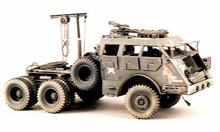
Step 25. The winch is a very highly detailed unit on it’s own with all the levers and springs as on the real thing, the base also acts as the anchor point for the ‘A’ frame supports and here I chose to do a little modifying.
The ‘A’ frame will be locked down if assembled as per instructions so before adding the arms (parts H13) I drilled the pairs of holes, represented on the sides, right through with a 0.75mm drill bit. One of the main steel axles was then placed inside the brass tubing and a centre punch used to mark out the corresponding holes in the tube at 4,7 and 20,23 mm from the rear end, I used the drilled arm to check alignment as I worked, then I used the 0.75mm drill bit to open the holes and cleaned up any swarf with a round file. I Slid the arm into the tube and lined up a pair of holes then locked one with a pin and used the drill bit to check the alignment of the other, this allows for any slight error in drilling. The ‘L’ shaped pins were made from flower wire bent to shape.
The pins on the end of the arms were cut off and a 1.25mm hole was drilled at that spot, the holes in parts H7/8 were also enlarged after they were cemented to the frame and pieces of 1.25mm rod were heated to form rivet heads then cut short making a tight fitting pins to lock the arms to the frame. When the pin is pulled the frame can be raised and the arm can be locked to the other side as on the real truck and adjusted to the required position, useful in dioramas.
Step26. I have built my crane up as intended and added the hoist with it’s delicate chain links, I also added the end stop pin from fine wire but I could have cut off the block on top of the upright post and had the same pivot as the real thing so it could be stowed away on the trailer.The trailer is simplicity itself with the main frames being screwed together trapping two steel reinforcing plates inside along with the metal hinges for the rear loading ramps, the etched metal sheet provides the treadplate steps on each side of the step frame. Tamiya’s poly caps are used to make and mount the suspension and of course add the wheels.
the suspension works in all directions as on the real thing
One little point to make, in step 30 when assembling parts M29/J33/M30 make sure that the two J33 parts are not cemented together as these must be independent for the rear loading ramps to move separately.
PAINTING is fairly straightforward, the whole thing is olive drab, I used Xtracolor X112 all over then I gave a light coat of X113 faded olive drab on top surfaces thinking these would suffer first from the exposure to the sun,
I left the wheels off until all the basic paint was sprayed then the tyres were added and mounted on the vehicle. Decals were put in place, the sub assemblies were added to make up the whole model and a light coat of floquil dust applied after which floquil mud was generously sprayed around the wheels and tyres and some undersurfaces where it would be likely to be thrown up. The cab shell had the windows and all the canteens etc. etc. added after the weathering was finished and mounted up. Where all the equipment goes is entirely up to the individual but there are stowage points for the wheel guards and bottle jacks if you care to use them, the possibilities here seem endless, after I had added the blankets to the engine cover with wine bottle foil straps I decided to put new camouflage netting on the roof of the cab, for this I used a strip of gauze bandage with the edges folded in then rolled and painted again with foil straps and etched brass buckles from the spares box.
a bit of dust and mud makes all the difference,
oh by the way the tank belongs to Terry Wills (fine modeller)
don't let anybody think I build targets
Summary: an excellent model to build with no problems that I could find, good fitting parts and plenty of choice on how to display the model, value for money? I suppose it must be, working on the enjoyment and time factor it took me four full days just to assemble the tractor unit without painting so that must be a lot of evenings for most people, it must be cheaper than going to the pictures. I only occasionally build AFV’s these days but I must say I have thoroughly enjoyed this one. A Tamiya anniversary special I am told let’s hope we don’t have to wait another 30 years for the next one as good as this.