
Dynavector
Gloster Javelin FAW.9
Early RAF fighter
Kit No. 4805. 1:48th scale
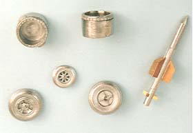
On
the left are some of the metal
parts, the fins on the missile are from the brass etched
sheet which also includes the vortex generators seen on the right, I have only added
those outside the area of the roundel (drawn in pencil) the remainder were added
afterwards and painted accordingly
sheet which also includes the vortex generators seen on the right, I have only added
those outside the area of the roundel (drawn in pencil) the remainder were added
afterwards and painted accordingly
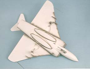
Just checking the seams
here but
note, I have not used any filler at all as the fit is good.
The instructions say no
noseweights are needed but I found I needed quite a
bit after the exhausts
were fitted
but there is plenty of room in the nose
for
lead shot so be warned

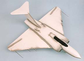
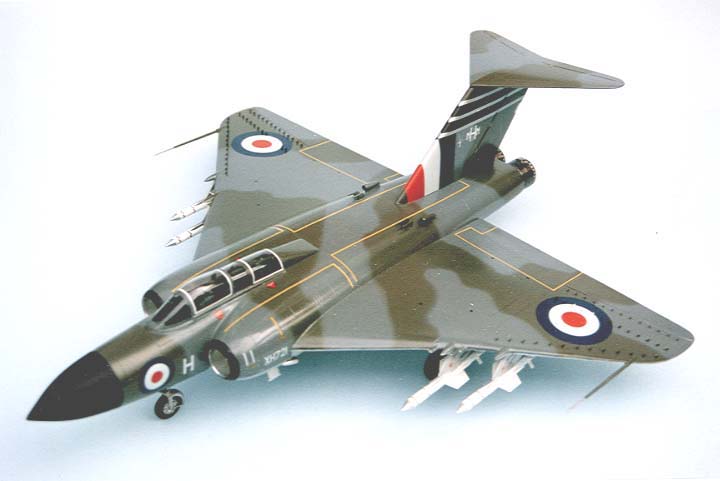
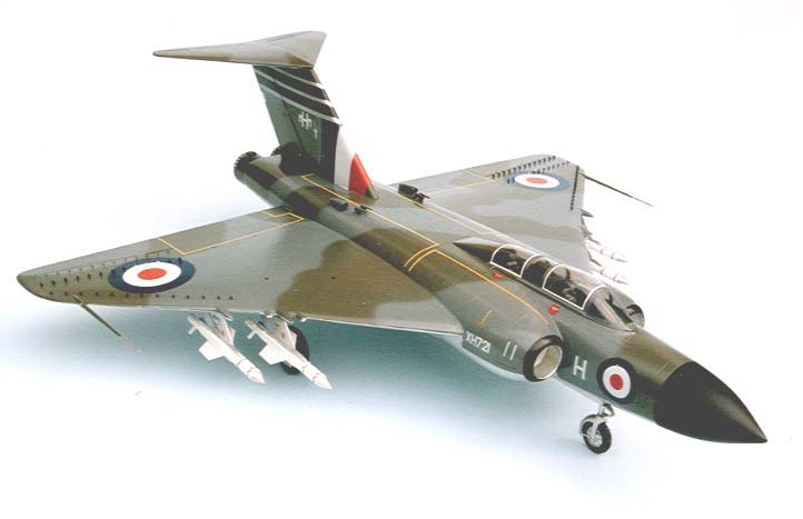
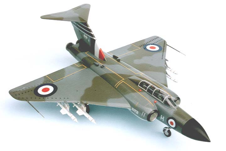
These four views
show only one of the four sets of markings in the box the others are for
25,33 and 64
squadrons.
For some unknown reason I have always had a soft spot for the Javelin, in my early modelling years I built a flying model from balsa wood and I remember having the life frightened out of me one night on the A5 trunk road as one took off from an airfield right over my head as I was driving by, but I think I just like the shape really.
I have had the kit on the shelf marked “to be done” for some time now and when the Hornet came in I indulged in an eighteen day binge on vacforms making the Skyshark as well, one reason for this is whilst it is not difficult it can be a messy and dusty process cutting and sanding out the parts so I got it all over in one go before starting on construction of any.
The kit contains the usual sharply moulded major components with the fuselage split on the horizontal plane and a bag full of white metal parts (45 pieces in all) which include cockpit consoles and instrument panels, undercarriage legs and wheels, pylons and missiles plus intakes and exhausts. The nice surprise was to find a sheet of etched brass in the box providing realistic vortex generators and missile fins and of course you get the extra canopy moulding in case you make a boo boo on the first. A large decal sheet provides for four different aircraft form 25,33,60 and 64 sqdns, and the instruction sheets are basic at least but adequate for a modeller with a little experience.
Construction Notes
The cockpit bathtub was cut out and built up and checked into the top shell and when satisfied I detailed and painted it fully except for the seats, which were added later, then, glued the tub in position.
The fuselage was constructed as per the instruction sheet, dropping in the stiffeners as recommended (a useful trick here) but I also added some 20thou tabs along the sides of the nose/cockpit areas and engine bays, to not only help locate the top half of the fuselage but to add strength as well. One thing of importance here the sheets say no balancing weights needed in this model but when those metal exhausts are added you most certainly do need weights, I found out the hard way and had to drill a hole below the nose and fill it with lead shot before sealing and repairing so be warned.
The metal air intakes were brushed up and polished before adding the inner trunking then the hole in the front of the engine bay was carefully cut away (this is where those extra strengthening tabs came in useful) until the intake just slid into position, I then superglued it and had to sand it a little to match up to the plastic of the engine bay.
I like the way the wheel bays are done as separate items, it means you have more detail and greater strength in the wing itself. Don’t worry about the gear doors you remove as fresh ones are supplied to replace those cut out, the holes for the pylons were cut out by drilling a small hole at each end of the marked area and joined up with a scalpel blade, a thin flat file was then used until the pylon was a nice tight fit.
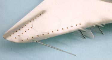
I used a drill of the recommended size 0.45mm to make all the holes for the vortex generators then I cut one of the upper wing roundels out and laid it in position on the surface and drew around it with pencil, next the tiny brass generators were pushed into each hole with tweezers and a thumb nail (no need for glue here as the paint will hold them firmly) working inboard to outboard for comfort excluding those in the roundel area, these would be added and painted to match the roundel colours later. Take care to line each piece up with the marks on the surface, this turned out to be not so daunting as I first supposed and was done in less than an hour and the result looks fantastic I thought.
You are asked to make four wing stiffeners but not advised where to mount them so I slid one in either side of the main wheel bay until it touched both surfaces and glued each to the bottom wing half only, one did have to be shortened slightly. When hardened off the inside edge of the wings were scraped to match the “mounting stubs” on the fuselage and cemented in position between the locating marks on the sides, I used a little drop of Humbrol liquid poly here to ensure a close fitting strong joint. Take note that the wings are horizontal (have 0 degrees dihedral) so use the tail fin and stabiliser to ensure all is squared up when viewed from the front, very important this. All the joints were later sprayed with light grey paint to check for problems, there were none and no filler whatsoever was used so the canopy was added with PVA glue and masked off. Various other parts were added and the silver undersides were sprayed using Humbrol polished aluminium (not polished) this was then coated with Johnson’s Klear to seal it.
The sides of the fuselage were then masked in the appropriate places and the underside of the stabiliser also. The nose cone was sprayed with Humbrol 85 semi gloss black and masked as well before the main camouflage was sprayed on freehand keeping the airbrush as close to the surface as possible to keep the demarcation sharp. Later a coat of Klear was added all over to get that smooth finish ready for the decals and there are lots of them, a few of the small stencils showed signs of silvering so I lifted each one and placed a tiny drop of Klear under it and as it dried of I rolled a finger across it to remove the excess and wiped it away, no more silvering. When I was finally satisfied I coated the whole surface again with Klear giving a nice sheen, I am often asked if I spray or brush Klear on well I do both depending how big the job is, if it just a wing I might brush it but a full plane I would probably spray it. From here on you can add a matte varnish if you wish but I preferred not to. Finally with the exhausts and pitot tubes added and up on its wheels the model was finished looking very impressive I think you will agree.
Ted Taylor
An excelent article on Vacform Modelling can be found Here
#Back to the Top
| Last
Page |
Airbase |
What's New |
Home |
Reviews |
Next Page |